
Car phone mount stability and vibration performance
Car phone mount stability refers to the ability of a car phone mount system to control movement through its holder, base, arm, grip, and mounting position under normal driving conditions. It describes how effectively the setup manages vibration, road movement, shaking, and phone retention while keeping the device readable and secure. Stability is directly linked to how well the holder structure balances base contact and grip strength against continuous driving forces.
In real driving conditions, vibration from the road can transfer through the base and arm of a car phone mount and create visible shaking in the phone. This movement can affect screen visibility and reduce the steadiness of phone retention, especially when phone weight, case thickness, and grip balance are not aligned with the mount structure. When vibration, grip security, and visibility are not working together, the overall stability of the phone holder can become inconsistent during use.
The scope of car phone mount stability also includes how different mounting points interact with road movement and structural leverage across the holder system. Stability is not only about one component but the combined behavior of base contact, grip response, and vibration transfer across the full setup. This creates a broader understanding of how the system performs across different driving environments. car phone mount hub
Because stability varies by mounting conditions, phone characteristics, and driving surfaces, outcomes are not identical across all setups. A car phone mount may perform differently depending on how its base, grip, and arm structure interact with vibration and road movement in real use.
What stability means for a car phone mount
Car phone mount stability is the mount’s ability to keep the phone readable, retained, and controlled while the vehicle moves. It describes how the holder, base, and grip work together to manage vibration, road movement, and steady viewing without losing phone retention. In practical use, it reflects how securely the phone stays positioned during normal driving conditions.
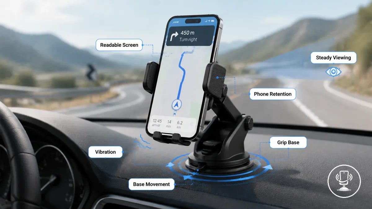
This stability connects directly to how vibration and base movement travel through the mount structure and affect steady viewing. When the grip is properly aligned with phone weight and case size, the phone can stay readable while still experiencing minor controlled movement from road conditions. The balance between grip force, holder arm support, and mounting base contact determines how much motion is transferred to the screen.
Car phone mount stability is also not the same as installation position or general device quality alone, because movement control depends on how multiple components interact under driving vibration. Even stable setups may still show slight shaking depending on road surface and phone load conditions.
Why car phone mounts shake while driving
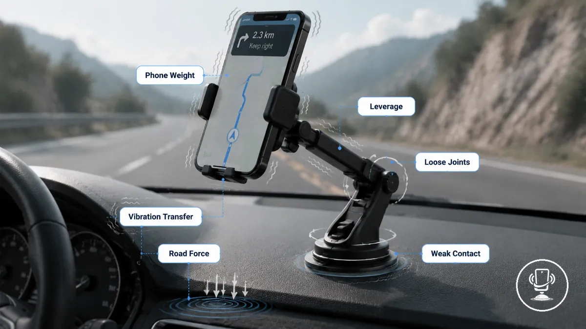
Car phone mount shake usually comes from vibration transfer, road force, leverage, loose joints, phone weight, weak contact points, and mount construction. These factors combine to create visible shaking when the vehicle is moving, especially on uneven roads or at higher speeds. The main causes are typically linked to how force travels through the mount system rather than a single failure point.
These causes interact through continuous vibration transfer from the road into the mount base and up through the arm structure. When leverage increases due to longer arm length or extended positioning, even small road force can become visible movement at the phone level. Phone weight and case thickness can further shift grip balance, while loose joints and weak contact points reduce the system’s ability to control motion consistently.
The relationship between road force, mount construction, and movement control can be understood by breaking down how each factor contributes to shake intensity and stability loss.
Before the table, the main causes can be mapped against their direct effect on shaking behavior during driving conditions.
| Cause | Effect on Shake |
|---|---|
| Road force | Triggers initial vibration transfer into mount system |
| Leverage | Amplifies visible movement through extended arms |
| Loose joints | Reduces structural control and increases wobble |
| Phone weight | Shifts balance and affects grip stability |
| Weak contact points | Allows micro-movement at base connection |
| Mount construction | Determines overall resistance to vibration transfer |
Road vibration and vehicle movement
Road texture, engine movement, braking, and cornering continuously generate cabin vibration that travels through the vehicle structure. When these forces reach the dashboard area, they create transmitted force that can affect how a car phone mount behaves during driving. In most situations, this transfer of movement becomes the starting point of visible shake and grip stress in the mount system.
When road texture becomes uneven or driving conditions change, vibration patterns shift through braking and cornering actions, increasing movement inside the cabin.
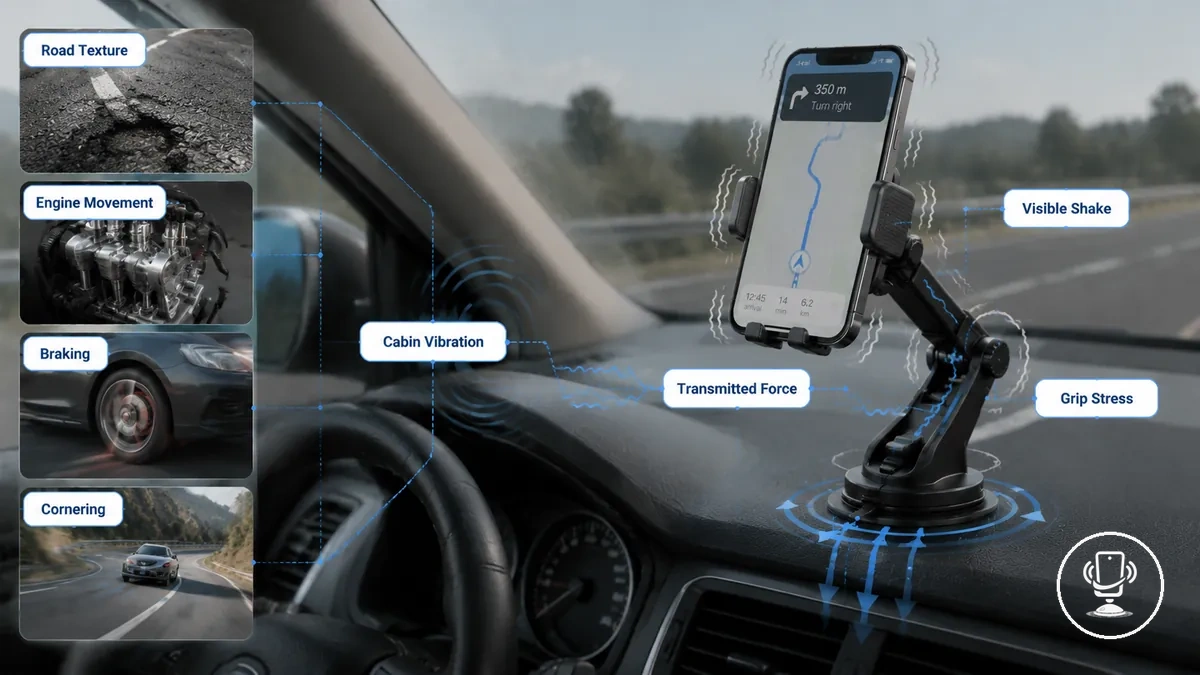
This transmitted force can create visible shake in the phone holder and increase grip stress depending on how the mount is constructed and positioned. Engine movement at idle or acceleration can also add low-frequency vibration, while cornering introduces lateral stress that changes how stable the phone appears during use.
- Rough roads increase transmitted force through the mount base
- Highway speed can amplify steady vibration patterns
- Braking shifts forward cabin movement and grip load
- Cornering introduces side-to-side shake and instability
- Engine vibration adds constant low-level movement
Arm length, joint stiffness, and leverage
Arm length, joint stiffness, and leverage describe how the support arm of a car phone mount transmits movement from the base to the phone position. When arm length increases or joint stiffness is lower, small cabin vibration can be amplified through leverage, making movement more noticeable at the phone end of the system.
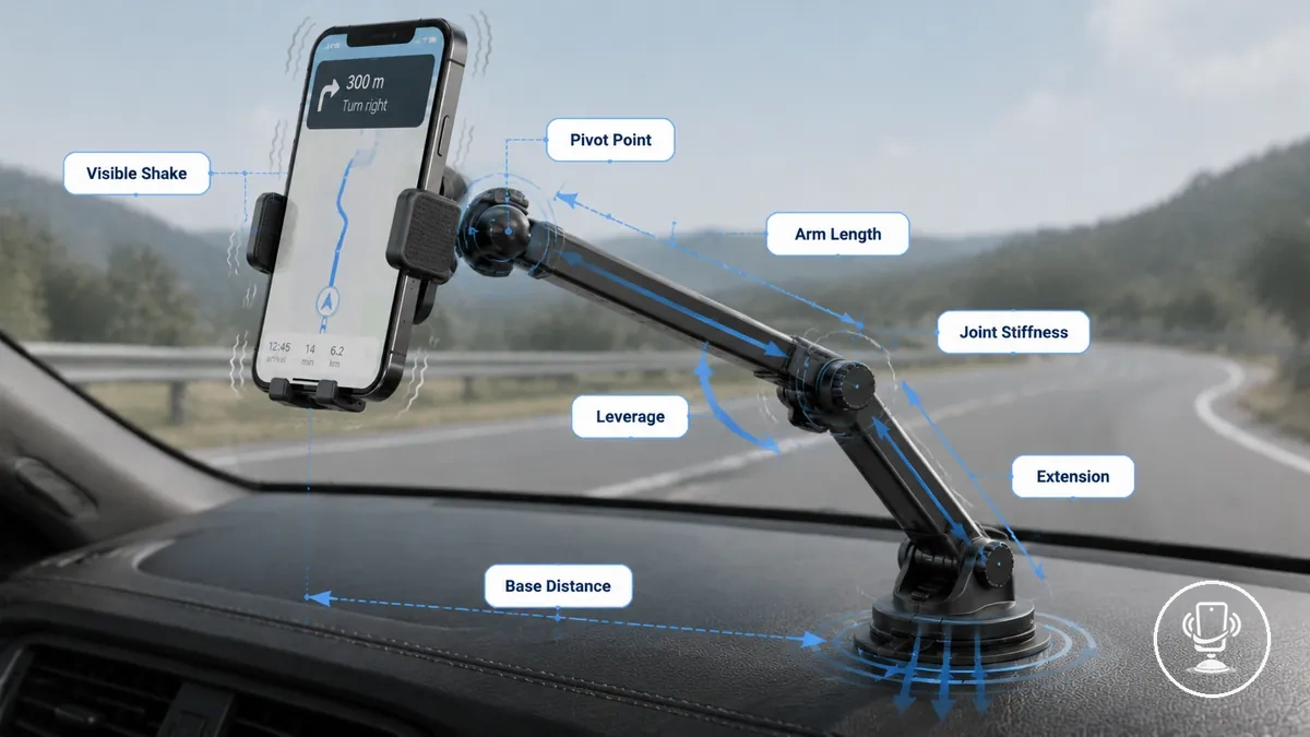
Longer extension and reduced rigidity change how force travels through the pivot point and adjustment joint of the mount. As arm length increases, leverage effects become stronger, and even small vibrations from the base distance can translate into visible phone shake. Joint stiffness and material rigidity also influence how much movement is absorbed or transferred through the structure.
- Long arm length increases leverage and movement amplification
- Lower joint stiffness can increase pivot point movement
- Reduced rigidity allows more flex under vibration load
- Greater extension increases sensitivity to cabin vibration
- Longer base distance can increase visible phone shake
Phone weight, case thickness, and grip balance
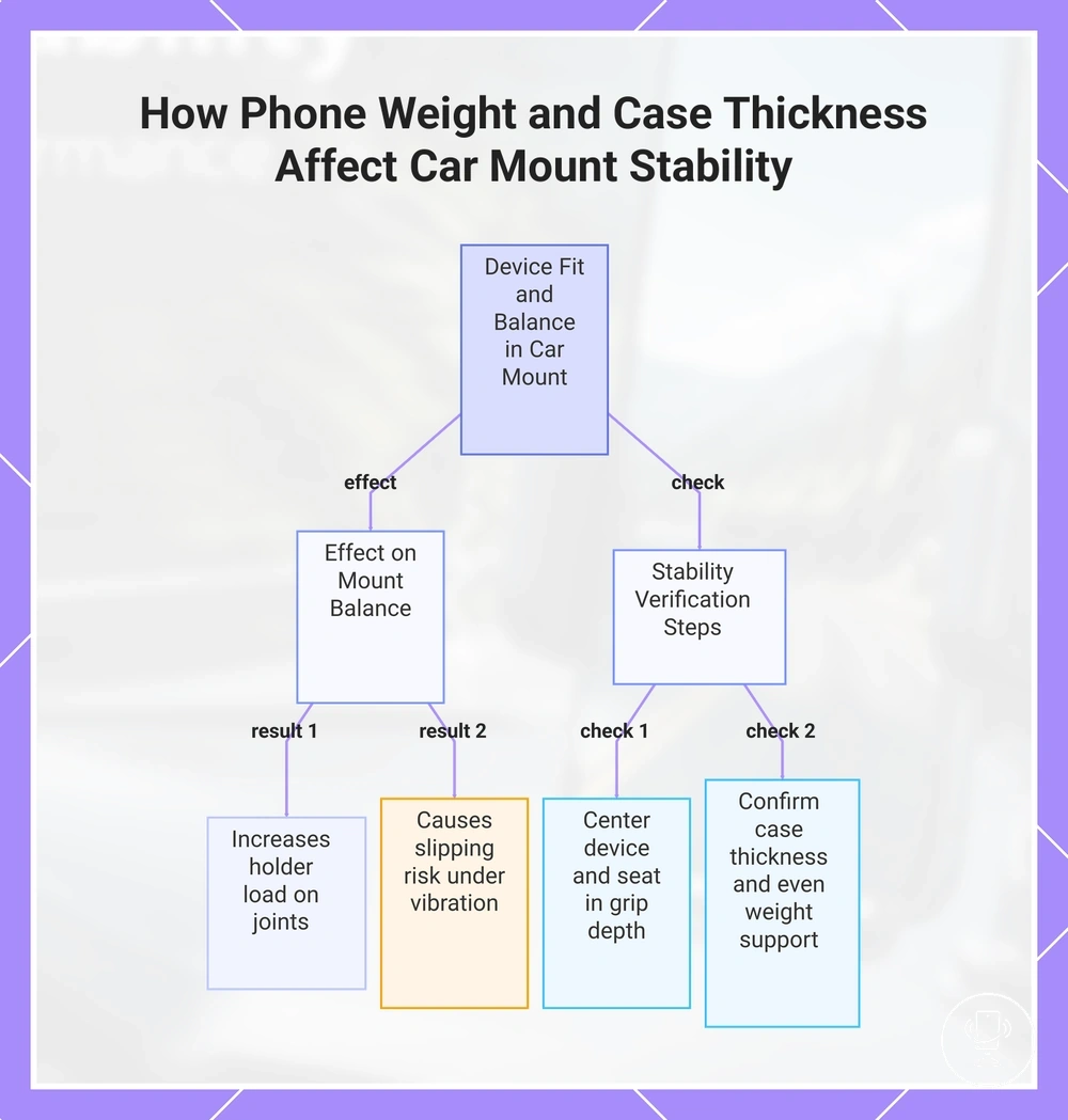
Phone weight, case thickness, and grip balance determine how evenly a device sits inside a car phone mount and how much holder load is placed on the joints. When the phone weight increases or the case thickness changes outer dimensions, the fit condition can shift slightly, affecting how securely the mount maintains center balance during movement.
Heavier phones or thick cases can change grip balance by pushing the device forward or downward inside the holder, which increases holder load on the support arm and joint points. When center balance is not aligned with the grip depth, the phone may experience slipping risk or minor movement under vibration, especially during braking or cornering.
- Check whether the phone is fully centered in the holder
- Ensure the device is fully seated within grip depth
- Confirm case thickness does not prevent stable contact
- Verify phone weight is evenly supported by both sides
- Observe any slipping risk during movement or vibration
This chart explains how phone weight, case thickness, and grip balance influence mount stability and lists the key checks to ensure secure positioning.
Mounting location and stability trade-offs
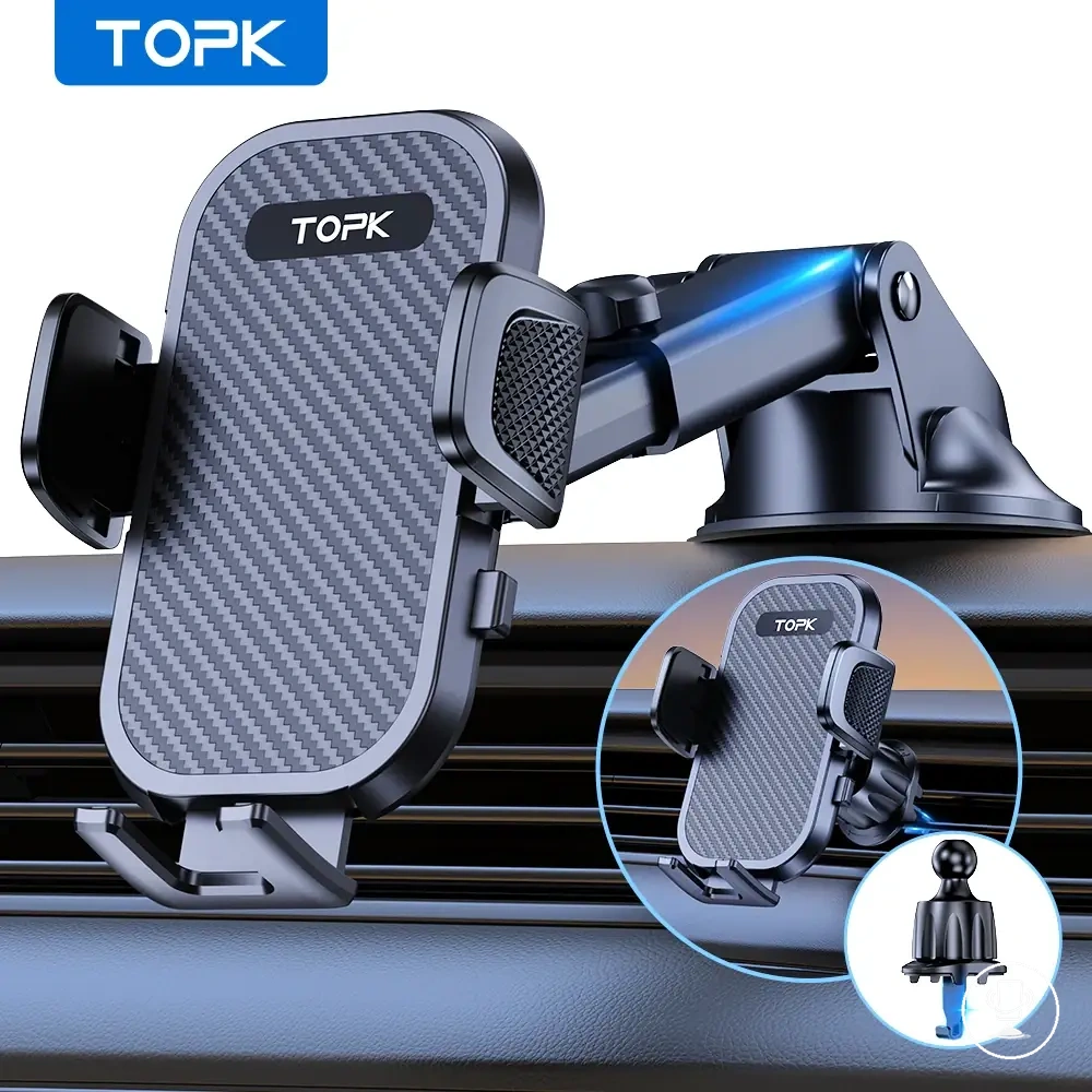
Mounting location depends on how the dashboard, windshield, or vent provides support surface and how each attachment method transfers vibration into the phone mount. The mounting location directly affects stability trade-off because each position changes movement patterns and how the phone is controlled during driving conditions.
A dashboard setup typically uses a stable support surface with shorter extension, which can reduce movement but still transfers road vibration through the contact area. A windshield setup relies on a suction-based attachment method, which can introduce longer arm movement and different vibration behavior. A vent setup uses clip contact on vent structures, which may vary in stability depending on vent resistance and phone load distribution. Each mounting location therefore creates a different stability trade-off rather than a universally optimal option.
| Mounting location | Support surface / attachment method | Movement pattern | Stability trade-off |
|---|---|---|---|
| Dashboard | Flat surface support contact | Short movement with direct vibration transfer | Stronger base stability but still affected by road vibration |
| Windshield | Suction attachment method | Longer arm movement with flexible swing | Higher visibility but increased motion sensitivity |
| Vent | Clip-based vent contact | Medium vibration influenced by vent movement | Compact setup but depends on vent strength and rigidity |
Dashboard base movement
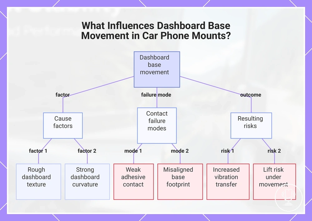
Dashboard base movement refers to how a car phone mount responds to dashboard surface texture and structural contact when it is placed on a mounting point. The dashboard and base contact determine how vibration is transmitted through the support condition, and this directly influences local movement during driving. In some cases, uneven surface contact can increase movement at the base and reduce stability consistency.
Dashboard texture, curvature, adhesive contact, and base footprint collectively shape how the mount interacts with the dashboard surface and how vibration or lift risk develops over time. A rough or uneven dash surface can weaken adhesive contact, while strong curvature may reduce full base footprint alignment. When base footprint and adhesive contact are not fully aligned with the support condition, vibration transfer can increase and lift risk may become more likely under movement load.
- Dashboard texture can affect how evenly adhesive contact spreads across the surface
- Curvature may reduce full base footprint alignment with the support condition
- Base footprint size influences how vibration is distributed across the dashboard holder
- Weak adhesive contact can increase vibration transfer and lift risk under movement
This chart shows the main factors that cause dashboard base movement, the resulting contact failures, and the associated risks.
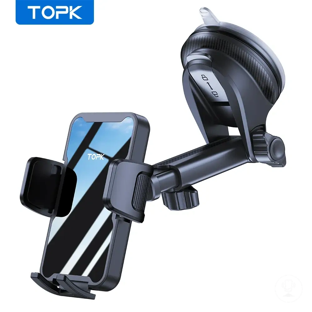
Windshield suction and arm movement
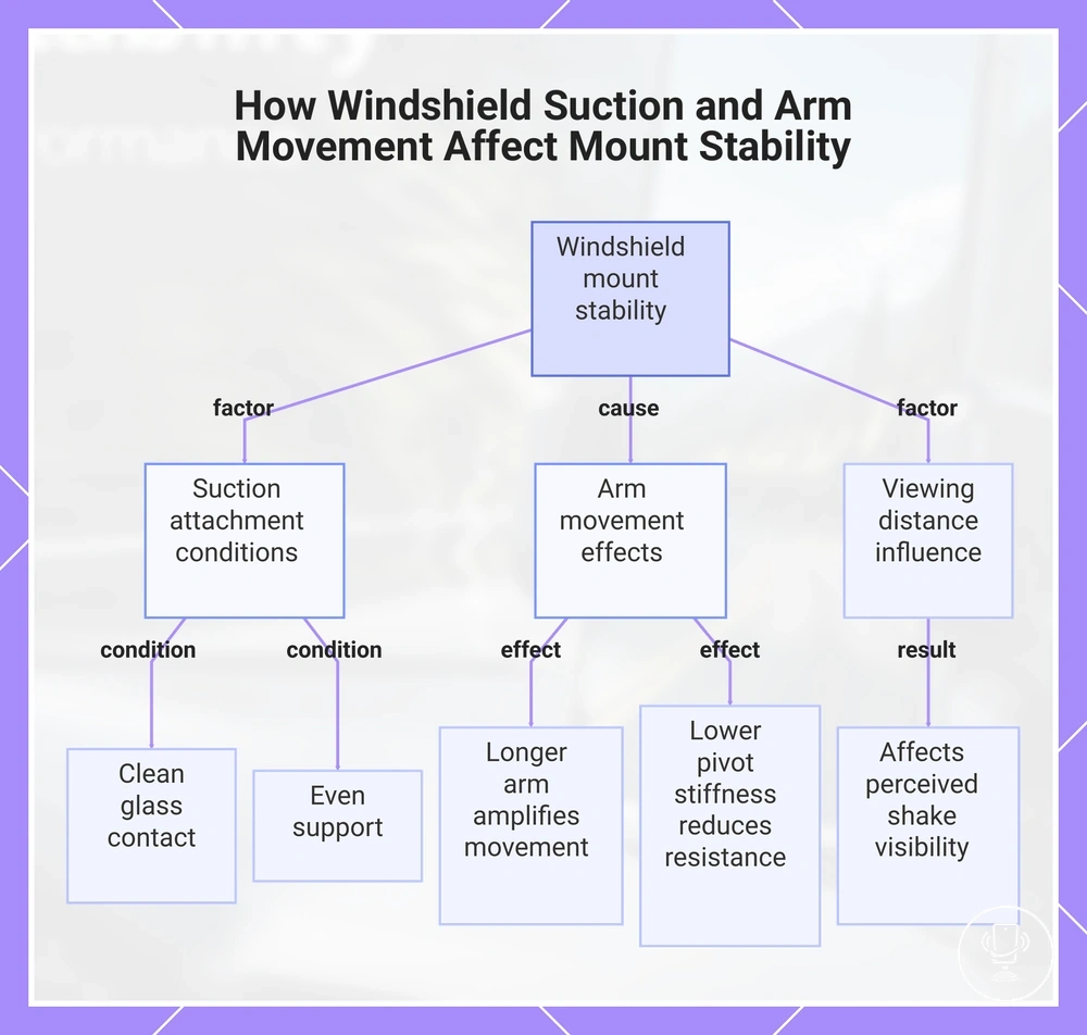
Windshield suction describes how a windshield mount uses suction seal and glass contact to stay attached to the windshield surface while supporting the phone during driving. The windshield and suction seal can create stable attachment when the glass contact is clean and evenly supported, but stability can still change when arm movement increases under vibration. This separates suction hold from motion behavior in the extended structure.
Arm length, pivot stiffness, and viewing distance are key variables that influence visible shake in windshield setups. A longer arm length can amplify movement transfer, while lower pivot stiffness can reduce resistance to vibration. Viewing distance also affects how visible shake is perceived, especially when small vibrations travel through an extended arm and impact readability on the display.
A secure suction seal does not always mean reduced movement if the arm structure is extended or less rigid. The balance between glass contact stability and extended arm behavior determines how much visible shake appears during use.
This chart shows the key factors that determine windshield mount stability, including suction attachment conditions, arm movement effects, and viewing distance influence.
Vent clip resistance under vibration
Vent clip resistance under vibration depends on how the vent clip engages with the vent blade and how clip depth and support hook distribute load during movement. In driving conditions, the vent structure and clip grip define the fit condition, which directly affects whether the mount stays stable or develops wobble. When the connection is not fully aligned, vibration can translate into rotational movement or slip outcome.
Vent blade strength, clip depth, support hook design, and phone weight all act as compatibility variables that influence how the vent clip performs under vibration. A stronger vent blade can improve resistance, while shallow clip depth or weak support hooks may reduce stability under load. Higher phone weight can increase stress on the vent structure, raising the chance of wobble or gradual slip outcome depending on the fit condition.
- Vent blade strength affects how securely the clip anchors under vibration
- Clip depth determines how deeply the vent clip grips the structure
- Support hook stability influences rotation control and wobble reduction
- Phone weight increases load stress on the vent-mounted holder
Anti-vibration design factors that improve stability
Anti-vibration design factors that improve stability depend on how multiple structural elements manage vibration transfer across the mount system. Stability increases when anti-vibration design reduces direct movement from base to phone and distributes force through connected components. These factors should be evaluated as criteria rather than ranked performance claims, since real-world results vary by conditions.
Anti-vibration design works through feature-to-condition-to-outcome relationships across key structural elements. Base contact influences how much vibration enters the system, while grip retention affects how securely the phone stays fixed during movement. Joint stiffness controls flex at pivot points, dampening material reduces vibration energy transfer, support geometry distributes load across the structure, and adjustment security helps maintain position under continuous motion. Each factor contributes differently depending on road vibration and mounting stress conditions.
The criteria below summarize how these design factors relate to stability outcomes under vibration exposure.
| Design factor | Condition | Outcome |
|---|---|---|
| Base contact | Strong mounting surface connection | Reduced vibration transfer into system |
| Grip retention | Proper phone fit and hold pressure | Improved device stability under movement |
| Joint stiffness | Low flex at pivot points | Reduced wobble during vibration |
| Dampening material | Absorbs vibration energy | Lower transmitted shake |
| Support geometry | Balanced load distribution structure | Improved overall stability balance |
| Adjustment security | Locked positioning mechanism | Reduced loosening during motion |
Base contact and mounting strength
Base contact and mounting strength depend on how the mounting base aligns with the surface contact area and how evenly force is distributed across that contact during vibration. When base contact is stable, the system can reduce movement risk under driving conditions, but weak or uneven contact can increase instability as vibration transfers through the mounting base. This makes base contact a primary factor in controlling overall mounting strength.
Base size, surface contact quality, adhesive hold or suction hold, and pressure distribution determine how force is handled at the mounting point and how movement risk develops during vibration. A larger base size can improve load distribution, while uneven surface contact can concentrate stress and increase instability. Adhesive hold or suction hold performance depends on consistent pressure distribution, and any imbalance in this system can increase vibration transfer and raise movement risk under real driving conditions.
Verification checklist for base contact stability:
- Check that base size matches the available mounting area
- Ensure surface contact is clean and evenly aligned
- Confirm full surface contact across the mounting base
- Verify adhesive hold or suction hold is evenly applied
- Assess pressure distribution for signs of imbalance or movement risk
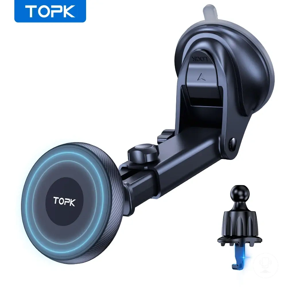
Phone grip strength and retention
Phone grip strength and retention depend on how side arms, clamps, magnets, pads, and lower support interact with the phone fit condition during movement. When the holder mechanism matches the phone size and case shape, retention improves and the device stays stable under vibration, but mismatched phone fit condition can reduce grip strength and increase slipping risk. This relationship makes retention a key stability criterion in real driving conditions.
Grip strength is shaped by how each mechanism maintains contact and distributes holding force across the device. Side arms and clamps typically rely on physical compression, magnets depend on alignment and contact area, pads add friction support, and lower support helps reduce downward movement. If the phone fit condition changes due to case material or size variation, retention may weaken and slipping can occur depending on vibration intensity and mount design.
Retention mechanism criteria:
- Side arms influence lateral grip strength and side-to-side stability
- Clamps affect compression force and overall holding force
- Magnets depend on alignment quality and contact area
- Pads increase friction-based retention under vibration
- Lower support reduces downward shift and improves retention balance
Dampening pads, stabilizers, and rigid support
Dampening pads, stabilizers, and rigid support influence how a phone mount manages transmitted vibration and structural movement during driving conditions. Dampening pads reduce transmitted vibration at contact points, while stabilizers help limit small shifts within the mounting system. Rigid support controls structural integrity by reducing excessive flex across the frame and support arms. Stability emerges from the balance between vibration control and structural resistance rather than from a single component.
Dampening pads, stabilizers, support arms, joint resistance, and material stiffness work together as movement-control attributes within the mount system. Dampening pads reduce vibration transfer, stabilizers help maintain alignment under motion, and support arms distribute load across the structure. Joint resistance affects how much movement occurs at connection points, while material stiffness determines how strongly the structure resists deformation. Rigid support contributes to limiting excessive flex, but its effectiveness depends on how these attributes interact under real vibration conditions.
How to test phone mount stability before driving
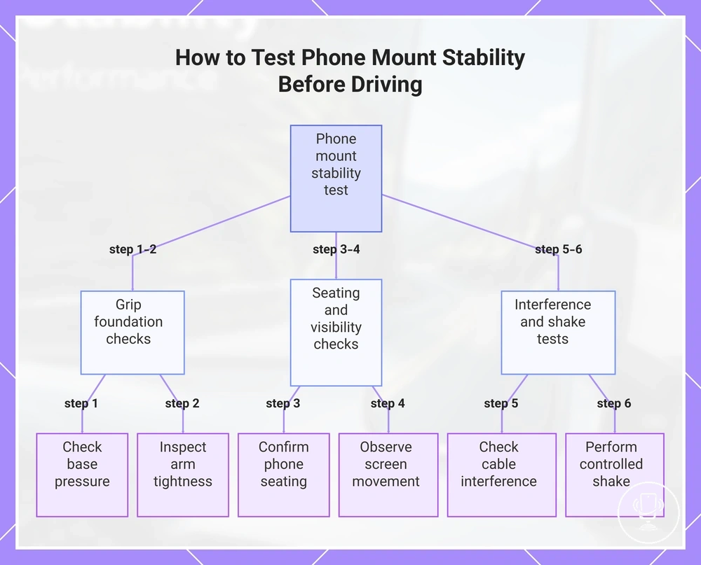
A stability test is a pre-drive check that evaluates whether a car phone mount remains secure, readable, and properly aligned under normal vehicle movement. It focuses on grip strength signals such as base pressure, arm tightness, and phone seating to identify early instability. This pre-drive check is always performed while the vehicle is stationary before driving.
The pre-drive check assesses whether the mount can maintain stability under light manual interaction and expected vibration conditions. Key criteria include base pressure consistency, arm tightness at all joints, correct phone seating, screen movement visibility, possible cable interference, and response under controlled shake. These indicators help determine whether adjustment security is sufficient for normal road use.
Stability test steps (pre-drive check):
- Check base pressure to confirm the mount is firmly attached to its surface
- Inspect arm tightness and ensure all joints resist unwanted movement
- Confirm phone seating is centered and fully locked into the holder
- Observe screen movement for wobble or readability changes
- Check cable interference that may pull or destabilize the phone
- Perform a controlled shake to detect looseness or vibration response
Heavy phones, thick cases, or long windshield arms can change stability behavior during the pre-drive check. In these cases, controlled shake sensitivity, phone seating depth, and arm tightness become more important, since small flex or uneven load distribution may increase movement under normal driving conditions.
This chart outlines the six step-by-step pre-drive checks to evaluate phone mount stability, covering grip foundation, seating, and shake tests.
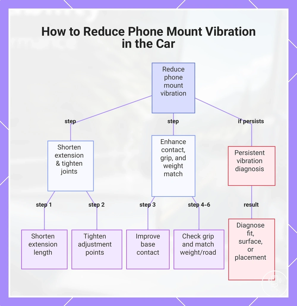
How to reduce phone mount vibration in the car
Phone mount vibration can usually be reduced by shortening extension length, tightening joints, improving base contact, and matching the holder setup to phone weight and road use conditions. These actions reduce vibration by controlling movement sources rather than removing vibration completely. In most cases, the goal is to reduce vibration to a stable, readable level before driving.
Vibration occurs when multiple structural and usage factors interact during road use. A long extension can amplify movement, loose adjustment points can increase joint play, weak base contact can transfer road vibration directly, and mismatched grip fit or phone weight can intensify instability. Road conditions such as uneven surfaces or frequent braking can further increase movement load on the mount system.
1. Shorten extension length to reduce leverage and limit shaking from long arm movement.
2. Tighten joints and adjustment points to reduce looseness and improve structural control.
3. Improve base contact by placing the mount on a stable surface with even pressure distribution.
4. Check grip fit to ensure the phone is held securely without shifting during vibration.
Here are product examples that may make comparison easier. Before buying, always review the compatibility criteria, essential features, and product details.


5. Match phone weight and case type to the holder’s supported load range to reduce imbalance.
6. Consider road use conditions, as rough surfaces or frequent braking can increase vibration even with correct setup.
If vibration continues after these adjustments, it may indicate a fit issue, weak mounting surface, or placement problem that requires diagnosis rather than further tightening or repositioning alone.
:contentReference[oaicite:0]{index=0}
This chart shows the key adjustments to reduce phone mount vibration and how to diagnose persistent issues.
Reduce extension and tighten adjustment points
Excess arm extension and loose adjustment points increase vibration by amplifying leverage through adjustable joints and reducing control at key connection points. Reducing arm extension and tightening adjustment points helps stabilise the support arm before evaluating vibration again, focusing on controlling movement at the source rather than changing the entire mount setup.
Stability improves when key adjustment components are secured in a controlled sequence before reassessing vibration levels.
- Telescoping arms: Shorten arm extension to reduce leverage and limit shake from extended reach.
- Ball joints: Tighten ball joints to reduce unwanted directional movement while maintaining basic adjustability.
- Rotation collars: Secure rotation collars to prevent gradual loosening during vibration exposure.
- Locking knobs: Set locking knobs firmly to stabilise position without relying on over-tightening.
- Hinge tension: Adjust hinge tension to balance resistance and controlled movement.
Re-seat the base on a stable surface
Re-seating the base on a stable surface improves mounting stability by restoring proper contact, seal, and surface pressure when the original placement becomes uneven or weak. When the base shifts or loses alignment, vibration can increase during use, so re-seating helps re-establish controlled contact before further evaluation. This action should be performed in a stationary setup with the phone removed to avoid load stress on the mount.
Start by ensuring proper surface conditions before adjusting contact and pressure points.
- Remove the phone first to prevent weight from affecting alignment and surface contact.
- Clean the stable surface to improve contact quality and remove dust that weakens adhesion.
- Place the base flat to maximise full contact and reduce uneven movement across the mounting area.
- Apply suction or adhesive pressure evenly to restore proper seal and surface pressure balance.
- Check dashboard texture to ensure it does not interrupt contact or weaken adhesion strength.
If repeated detachment, lifting, or loss of hold continues after re-seating, it usually indicates a deeper surface or fit issue rather than a simple positioning problem and may require further diagnosis through the falling-off instability path.
Match the holder to phone size and road use
Matching holder fit to phone size and road use reduces avoidable shake by aligning holder fit with how the device behaves under driving conditions. When phone size, case thickness, and grip depth are not aligned with the holder fit, vibration can increase and reduce retention outcome during road use. Proper alignment helps stabilise center balance and limit unnecessary movement during driving.
Use this checklist to evaluate whether the holder fit matches phone size and road use conditions before relying on it in motion.
- Phone width: Check that the holder supports the full phone width for stable grip distribution.
- Case thickness: Ensure case thickness does not reduce grip depth or push the phone off center balance.
- Center balance: Confirm the phone sits centrally to reduce uneven vibration during road use.
- Grip depth: Verify the holder provides enough grip depth to prevent shifting.
- Road use: Match holder fit to expected driving conditions to maintain consistent retention outcome.
This evaluation improves stability by linking phone size and holder fit to vibration behavior, while avoiding turning the process into a product selection or buying list.
When shaking signals a grip, surface, or placement problem
Shaking signals a grip problem, surface contact issue, or placement problem when movement becomes stronger than normal vibration and begins affecting stability or visibility. Minor vibration can occur under road use, but diagnostic shaking suggests a structural issue involving grip problem, surface contact weakness, or placement problem. This section separates normal movement from instability-related shaking.
The diagnostic process focuses on linking symptom patterns to likely sources before any correction is applied. Each category reflects a different instability pathway, where grip pressure, surface bonding, or mounting alignment may be responsible. Identifying the symptom correctly helps determine the safe next action without repeating adjustment steps.
| Symptom | Likely source | Condition to check | Safe next action |
|---|---|---|---|
| Phone slip | Grip problem | Weak grip pressure or misaligned holder fit | Re-check grip alignment and seating |
| Base lift | Surface contact issue | Reduced adhesion or uneven surface pressure | Inspect surface contact stability |
| Rotating joints | Placement problem | Loose adjustment points or misalignment | Secure joints and re-align placement |
| Visibility disruption | Placement problem | Excess movement affecting viewing angle | Adjust positioning for stable visibility |
If shaking persists, stop using the mount until grip, surface contact, or placement issues are corrected, as continued use may increase instability under road conditions.
Vibration that affects screen visibility or phone camera stability
Vibration that affects screen visibility or phone camera stability occurs when movement control is not sufficient to keep the display readable or the camera stable during use. This becomes noticeable when screen visibility is reduced by shaking or when camera stability cannot maintain a steady frame. It signals a shift from normal movement to a visibility or camera stability disruption caused by mounting vibration.
- visible blur reducing screen visibility and readability
- oscillation indicating unstable movement control
- camera shake affecting phone camera stability during use
- touch difficulty caused by shifting screen position
- angle drift showing repeated movement of viewing position
:contentReference[oaicite:0]{index=0}
Movement that may lead to slipping or falling
Movement that may lead to slipping or falling occurs when grip retention, surface contact, or placement stability is no longer sufficient to hold the phone securely under vibration. This condition moves beyond normal shaking and becomes relevant when slipping, detachment, or phone drop risk starts to emerge during use. It reflects a transition from controlled movement to unstable positioning.
Risk depends on how grip retention, base hold, and road conditions interact under load. The following checklist highlights warning signs that movement may be progressing toward slipping or falling:
- base peeling indicating weakening surface contact and rising detachment
- suction edge lift showing loss of seal and potential slipping
- clamp loosening reducing grip retention and increasing phone creep
- phone creep showing gradual slipping under vibration load
- vent rotation leading to unstable support and shifting position
- sudden tilt indicating loss of movement control and increased drop risk
When these signs appear, the mount should be treated as unstable and not relied on during continued use until grip, surface contact, or placement stability is corrected.
:contentReference[oaicite:0]{index=0}