Vent clip phone mount stability and air vent compatibility
Vent clip phone mount stability refers to how securely a vent clip phone mount holds a device on a vehicle air vent system under different driving conditions, based on air vent compatibility, grip mechanism performance, vent blade structure, phone weight, and case thickness. It describes whether the connection remains stable or begins to shift, tilt, or loosen during use, especially when slipping forces act on the mount. Safe use depends on how well these elements align rather than any universal or fixed performance outcome.
Stability is shaped by multiple interacting variables that work together rather than independently. Air vent compatibility determines whether the vent blade structure can physically support the clip without excessive movement. The grip mechanism defines how force is distributed across the vent blade, while phone weight and case thickness increase the overall load on the system. Driving conditions such as vibration, braking, and road unevenness can further influence whether stability is maintained or reduced over time.
Users often question whether vent clip phone mounts will slip, damage vents, or fail to fit certain vehicles. These concerns usually depend on how the clip engages with the vent blade and how much load is introduced through the phone and case combination. In many cases, slipping or looseness is not a fixed outcome but a condition that emerges when compatibility and load balance are not properly aligned. Safe use therefore requires evaluating fit and load together rather than assuming consistent behavior across all setups.
For a broader overview of related configurations and design differences across mounting systems, refer to the car phone mount hub, which provides contextual grounding for how vent-based solutions compare within the wider category.
This section sets the foundation for understanding how vent clip contact points, load distribution, and air vent structure interact, before moving into more detailed explanations of grip behavior and stability mechanisms.
How vent clip phone mounts hold onto air vents
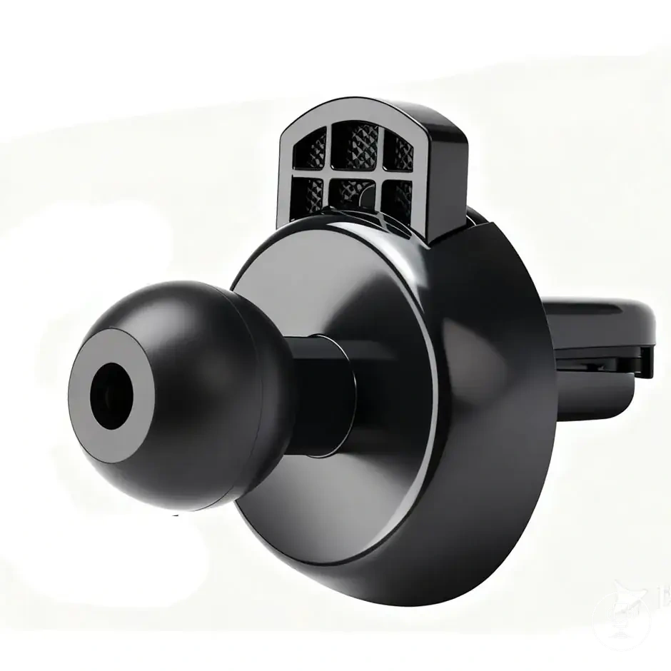
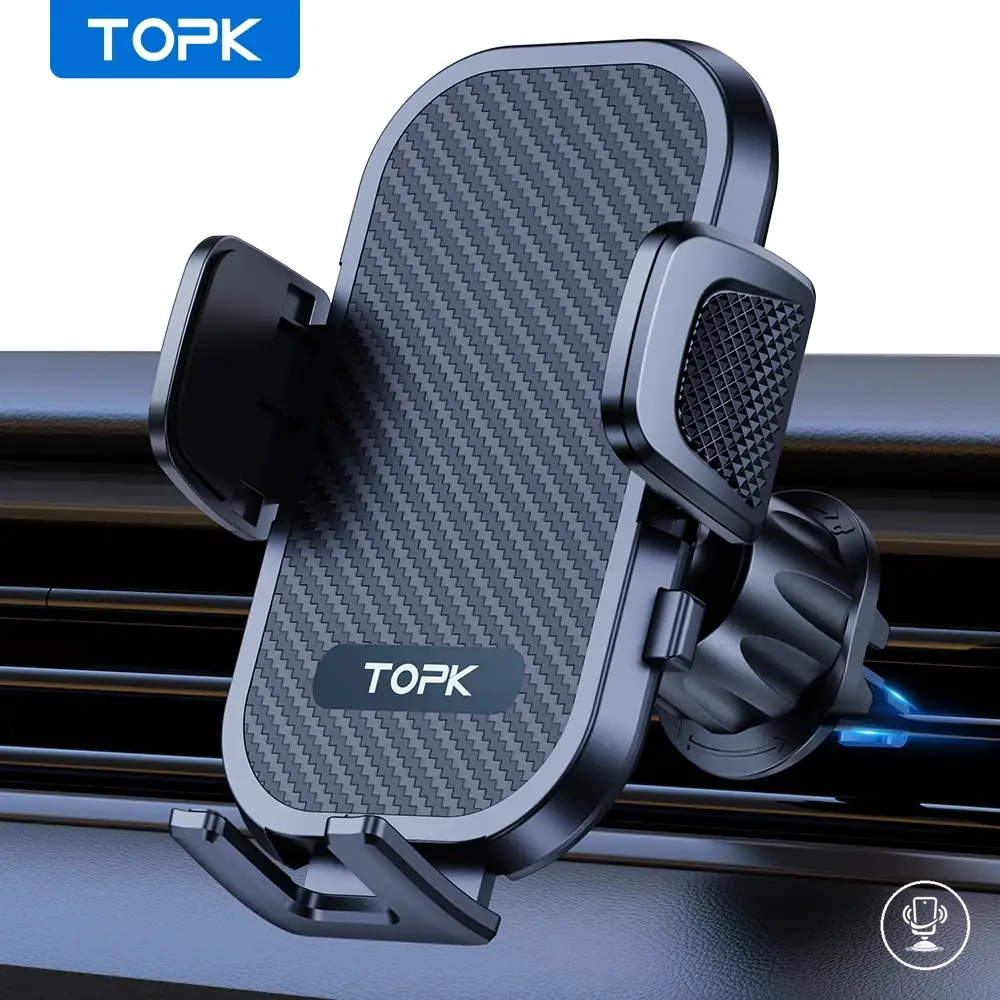
A vent clip phone mount is a car phone holder that secures itself to a vehicle air vent using a clip, hook, clamp, or braced grip mechanism. It holds position through physical contact between the mount body and the air vent structure, with the vent blade acting as the main support contact point.
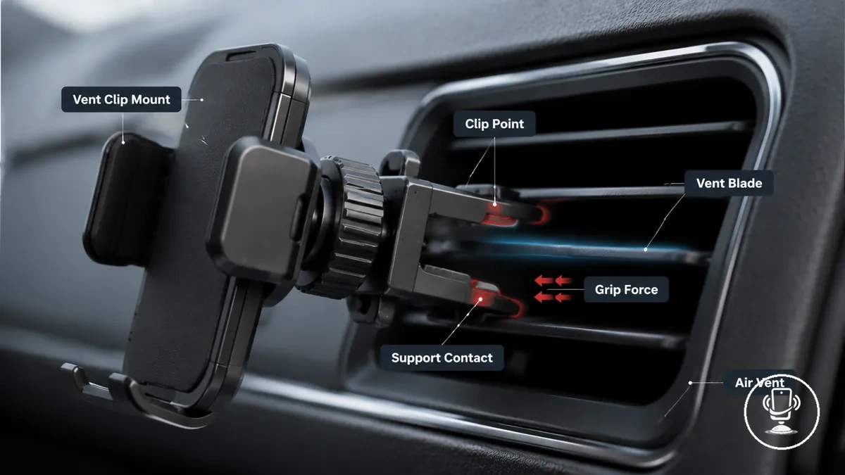
The way a vent clip phone mount holds onto air vents depends on a load path that starts at the phone holder body and transfers force through the clip point into the vent blade. The grip mechanism applies pressure at the contact areas to reduce movement, while stability is influenced by phone weight, case thickness, and vent blade structure. Fit and holding performance may vary depending on air vent compatibility and support contact conditions.
For example, a lighter phone in a slim case may remain steady when the clip distributes pressure evenly across the vent blade, while a heavier setup can increase stress at the support contact point and introduce movement if the vent structure is flexible. This shows that holding behavior depends on how grip force and vent support interact rather than following a single fixed pattern, preparing the transition into detailed grip-system behavior.
Hook, clamp, and prong grip systems
Hook grip, clamp grip, and prong grip systems are different vent clip phone mount mechanisms that secure a car phone holder to an air vent using distinct contact methods. Each system changes how load is held at the vent blade contact point, which affects stability limitation depending on fit conditions and vent structure.
Hook grip, clamp grip, and prong grip systems differ in how they create contact point pressure on the vent blade and how they manage load transfer across the vent structure.
- Hook grip: Uses a rear hook that anchors behind the vent blade. It can improve pull resistance, but stability limitation may appear if vent blade spacing is irregular.
- Clamp grip: Applies pressure across a wider contact area on the vent blade. It often spreads load more evenly, but may depend on blade thickness for consistent hold.
- Prong grip: Uses multiple small contact points aligned with vent blade gaps. It can reduce movement risk in well-aligned vents, but stability limitation may occur if spacing does not match.
Friction pads, rear braces, and contact pressure
Friction pads, rear braces, and contact pressure are secondary support elements in a vent clip phone mount that reduce slipping after the main clip has attached. These components work by adding additional support surface interaction between the mount body and the air vent structure. The friction pad material, brace position, and contact pressure each influence how force is distributed across the surface area, and they function as secondary support after the primary clip engagement.
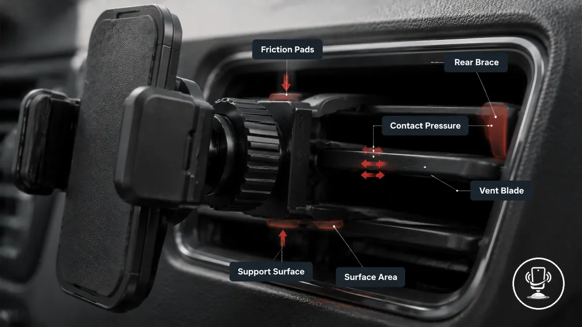
These secondary elements affect how the support surface responds to movement by adjusting pressure distribution and contact area on the vent blade and surrounding frame. Higher or uneven contact pressure may influence grip outcome in some setups, while reduced surface area contact may allow limited movement depending on vent condition and alignment. Their effectiveness varies by vent structure, so stability outcome depends on how these factors interact rather than a fixed result.
- Friction pads: Increase surface texture contact on the support surface, which can reduce slipping depending on material and vent condition.
- Rear braces: Stabilize the mount against the vent frame and may improve support contact when alignment is firm.
- Contact pressure: Distributes force across the surface area and influences grip outcome based on vent blade strength and spacing.
Source context file :contentReference[oaicite:0]{index=0}
Air vent designs that affect mount fit
Vent mount fit depends mainly on air vent design factors such as vent shape, blade strength, blade spacing, vent depth, and movement range. These physical conditions determine how securely a mount can attach and how stable it remains once installed, making compatibility dependent on the vent’s structural characteristics rather than a universal fit rule.
Air vent compatibility can be better understood by comparing different vent designs and their physical attributes. The table below organizes common vent types based on how their structure influences mount fit and stability effect, focusing on condition-based compatibility rather than vehicle-specific models.
| Vent design | Fit attribute | Compatible or risky condition | Stability effect |
|---|---|---|---|
| Horizontal slat vent | Even blade spacing and moderate strength | Generally compatible when blades are firm and evenly spaced | Often provides stable mounting contact |
| Vertical slat vent | Varied clip access and directional support | May be compatible depending on clip alignment and support angle | Stability may vary with load direction |
| Circular turbine vent | Non-linear shape and curved structure | Often risky due to limited secure contact points | Reduced stability due to uneven load distribution |
| Recessed deep vent | Deep-set frame with limited edge access | Risky when clip cannot reach stable support points | Lower stability due to restricted contact area |
| Thin fragile vent | Low blade strength and flexible structure | Risky under load from heavier mounts or devices | Stability effect may weaken due to flex movement |
Vent compatibility should be read as a conditional relationship between vent design and mounting fit, where each structure presents different support characteristics. This section evaluates vent fit based on physical conditions only and does not determine overall car phone mount selection or broader category suitability.
Horizontal, vertical, circular, and recessed vents
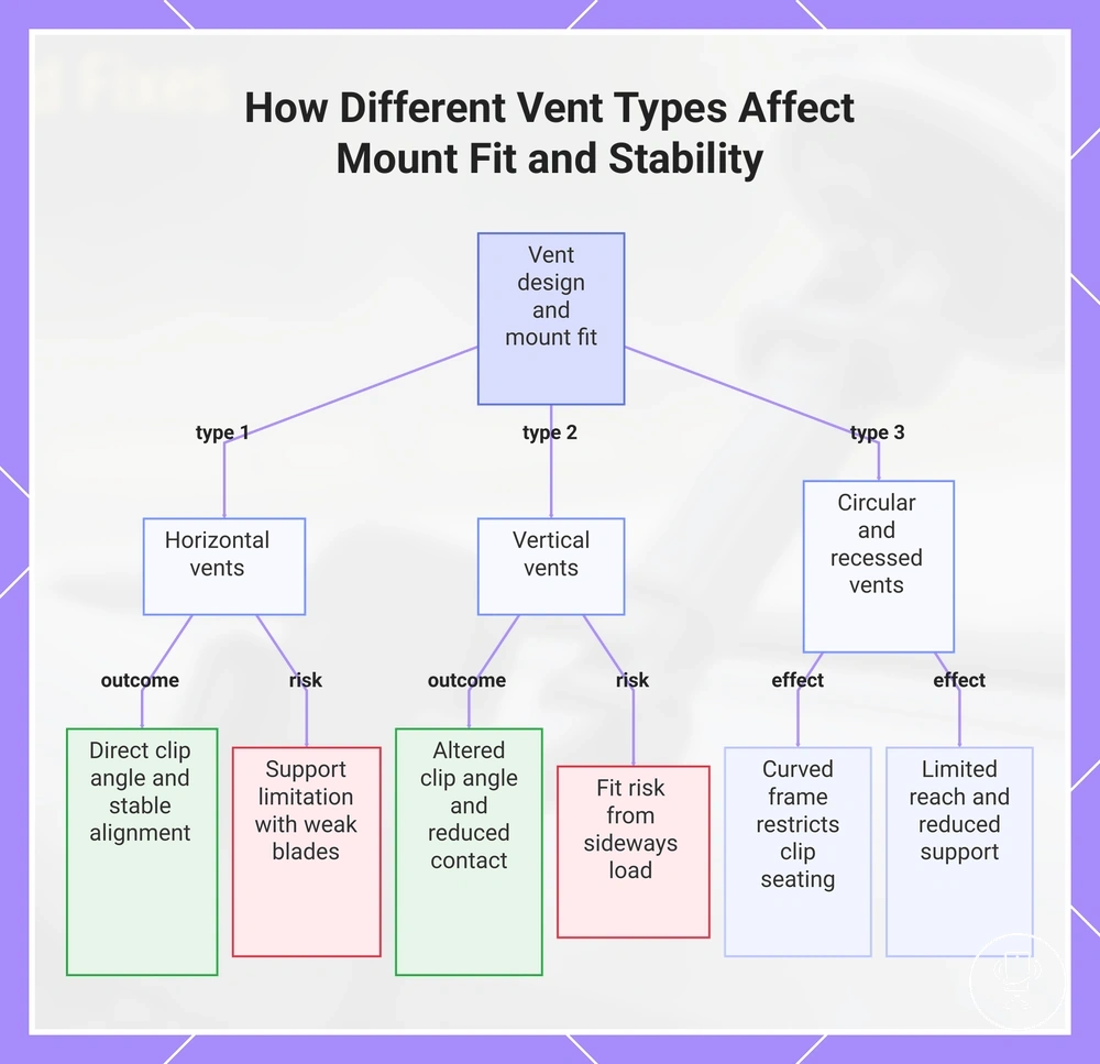
Horizontal vents, vertical vents, circular vents, and recessed vents influence mount fit by changing clip angle, contact access, and how the load is supported across the air vent structure. These air vent design differences affect compatibility because blade direction, frame geometry, and depth conditions directly shape mounting alignment and stability effect.
Vent layout changes how the clip engages with the vent system, especially through contact access and available support points. Each vent form introduces different constraints in clip angle and support limitation, so fit risk depends on how the mount design aligns with these physical conditions rather than a universal outcome.
The comparison below shows how common vent forms affect clip access and mounting stability in a compact condition-based view:
- Horizontal vents: Horizontal vents usually allow direct clip angle and stable blade alignment, though support limitation may appear with weak or widely spaced blades.
- Vertical vents: Vertical vents can alter clip angle and reduce contact access, with fit risk increasing when sideways load affects alignment.
- Circular vents: Circular vents may restrict clip seating due to curved frame geometry, where fit risk depends on depth and contact access.
- Recessed vents: Recessed vents can limit clip reach and reduce support contact, increasing fit risk when vent depth prevents secure brace engagement.
This chart compares how horizontal, vertical, circular, and recessed vent forms influence clip angle, contact access, and mounting stability.
Vent blade depth, thickness, and movement range
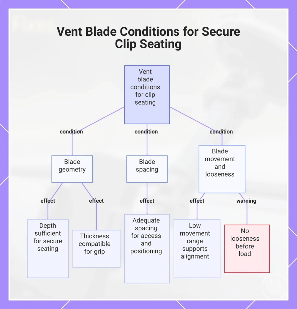
Vent blade depth, blade thickness, and movement range determine whether a vent clip can achieve secure clip seating on an air vent. These vent blade properties control how firmly the clip grips the structure and how consistently pressure is distributed, which directly affects the resulting stability result.
Blade movement range also influences how the system behaves under load, especially when the vent structure shifts before the phone weight is applied. Vent blade depth, thickness, spacing, and movement range together determine whether seating remains stable or whether looseness develops, so compatibility depends on these physical conditions rather than fixed outcomes.
The checklist below verifies key vent blade conditions that influence clip seating and stability result:
- Blade depth: Sufficient depth supports secure clip seating, while shallow depth may reduce engagement strength.
- Blade thickness: Compatible thickness allows proper grip, while very thin or overly thick blades may affect seating stability.
- Blade spacing: Adequate spacing supports clip access and correct positioning between blades.
- Movement range: Low movement range supports alignment stability, while higher movement may increase instability risk under load.
- Looseness: Any looseness before load application may reduce stability result and weaken overall seating reliability.
This chart shows the key vent blade conditions that determine whether a vent clip achieves secure seating, including depth, thickness, spacing, movement range, and pre-load looseness.
What makes a vent mount stable or unstable while driving
Vent mount stability depends on how force travels through the load path from the phone to the holder, then from the holder to the clip and into the vent structure. When this load path is balanced, vent mount stability remains consistent, but when it is uneven, wobble or slipping can occur under movement conditions.
Driving movement continuously affects this load path through changes in phone weight, case thickness, clip leverage, vent looseness, road vibration, and mount angle. On smoother roads, these factors may stay within stable limits and reduce movement impact, while on bumpy roads the same setup may show increased wobble depending on how each condition interacts with the vent structure and clip seating.
The table below explains how key factors influence vent mount stability, showing how each condition contributes to the stability effect. These factors combine and interact rather than acting independently in real driving situations.
| Factor | Condition | Stability effect | What to check |
|---|---|---|---|
| Phone weight | Higher or uneven load distribution | Increases downward force and potential slip | Balance on holder and clip support strength |
| Case thickness | Thicker or rigid case surface | Changes grip pressure and leverage on mount | Contact balance with holder arms |
| Clip leverage | Extended or angled clip reach | Can amplify movement under vibration | Grip tightness on vent blade |
| Vent looseness | Loose or flexible vent blades | Reduces structural support and increases wobble | Blade firmness before mounting |
| Road vibration | Uneven or high-frequency movement | Increases shake and micro-adjustments | Stability under driving conditions |
| Mount angle | Downward or off-center positioning | Affects balance and load distribution | Alignment with vent direction |
Phone weight, case thickness, and holder load
Phone weight and case thickness directly increase holder load on a vent clip and can influence vent mount stability when clamp contact and balance are not optimal. This combined load comes from the phone mass and case bulk pressing through the holder onto the vent clip.
The effect depends on case thickness, clamp contact, and the resulting center of gravity of the device on the holder. A thicker case can shift the center of gravity forward or outward, increasing leverage on the vent clip and changing how the holder load is distributed. In some setups, this may increase slipping or sagging tendencies when vent clip support and mounting balance are not aligned with the combined load.
- Phone weight: Increases direct holder load on the vent clip.
- Case thickness: Alters balance and can shift center of gravity.
- Clamp contact: Determines how evenly the vent clip distributes holder load.
Bumpy roads, mount angle, and loose vent fins
Bumpy roads, mount angle, and loose vent fins affect vent mount stability by changing how forces move through the mounting system, which can lead to shaking or slipping as downward force and leverage increase under motion. These conditions turn a seemingly secure fit into a moving load scenario where leverage and motion work together on the vent clip.
These driving and structural conditions influence how force is transferred through the vent clip during movement. Even when a vent mount feels stable while parked, bumpy roads, braking, and cornering can shift load distribution and introduce shaking or slipping depending on mount angle and vent fin stability. The effects are condition-based and are explained here as force behavior, while full corrective fixes are addressed in later sections.
The following cause-effect patterns show how each condition influences movement and stability:
- bumpy roads: road vibration increases downward force on the vent clip → results in shaking of the mounted phone.
- braking: forward downward force shifts through the mount → may lead to slipping or forward movement.
- cornering: lateral force changes load direction → causes wobble or shaking.
- mount angle: increased leverage amplifies downward force → can result in sagging or slipping.
- loose vent fins: vent structure moves under load → increases shaking and instability.
How to check whether a vent clip mount fits a car
A vent clip mount fits a car only when the clip seating is firm on the car air vent with stable contact on the vent blade, without excessive movement, blocked controls, or restricted airflow direction. The check fit process confirms whether the vent clip mount can maintain proper seating under real use conditions as the primary pass condition.
This check fit should be completed before adding phone weight, because even a stable seating test can change once load is applied. A proper compatibility check evaluates vent layout, blade strength, clip seating, holder clearance, airflow direction, control access, and any warning condition that may affect daily use. These criteria act as a seating test to separate usable installation from risky alignment.
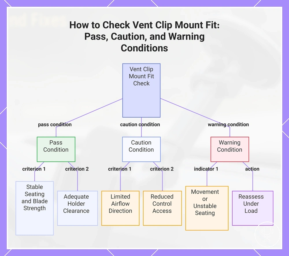
A vent clip mount is evaluated through pass, caution, or warning condition outcomes based on how the clip seating interacts with the car air vent. Strong clip seating with stable blade strength and adequate holder clearance usually indicates a pass condition, while limited airflow direction or reduced control access may indicate caution. If movement is detected in the vent blade or seating becomes unstable, the setup moves toward a warning condition and requires reassessment under load.
The following fit check checklist helps evaluate compatibility before full use:
- Clip seating: Confirm the vent clip mount locks firmly onto the car air vent without shifting during light movement.
- Blade strength: Check whether the vent blade maintains stability during a seating test.
- Holder clearance: Verify the mount does not interfere with surrounding dashboard space or controls.
- Airflow direction: Ensure airflow is not excessively blocked or redirected in a disruptive way.
- Control access: Check that essential vehicle controls remain usable without obstruction.
- Movement test: Observe any vent movement or looseness before adding phone weight.
This chart shows the three possible outcomes (pass, caution, warning) of a vent clip mount fit check, the key criteria for each, and the need to reassess under load.
Stable fit signs before placing the phone
Stable fit signs before placing the phone refer to observable conditions that confirm the vent clip mount is properly seated on the car air vent before any phone load is added. These stable fit signs help verify that the clip is seated correctly and the vent structure can support basic positioning before use. These checks are completed before phone load is added.
These checks reduce risk before phone load is applied, but they do not guarantee performance under all driving conditions. The assessment focuses on stable fit signs as a pre-load check.
- Clip seating: Clip seated with firm contact on the vent blade → indicates stable contact → expected benefit is reduced initial shifting.
- Vent movement: Limited vent movement during light touch → indicates stable structure → expected benefit is more consistent positioning.
- Centered support: Mount aligned with centered support on vent frame → indicates balanced load base → expected benefit is reduced tilt risk.
- Clear controls: Clear controls remain unobstructed → indicates proper clearance → expected benefit is safer daily use alignment.
- No twisting: No twisting under light pressure → indicates firm contact → expected benefit is improved seating stability.
- Pre-load test: Light check performed before phone load → indicates baseline stability → expected benefit is early detection of weak fit conditions.
Poor fit signs that predict slipping
Poor fit signs that predict slipping refer to early unstable fit signals where a vent clip mount is not properly secured on the car air vent and may begin to wobble or shift before phone load is applied. These poor fit signs often appear during the initial seating stage and should be treated as warning indicators rather than final failure confirmation.
- Loose blade movement: Vent blade shifts during light touch → likely cause is weak structural grip → risk is increased wobble and progressive slipping under phone load.
- Shallow clip seating: Clip does not fully lock onto car air vent → likely cause is incomplete engagement → risk is gradual detachment when vibration increases.
- Tilted mount position: Mount leans or sits off-angle → likely cause is uneven load distribution → risk is sliding or rotation during driving motion.
- Blocked brace contact: Rear brace does not fully touch vent frame → likely cause is misalignment or spacing gap → risk is reduced stability and forward shifting.
- Weak friction: Mount surface slips during light pressure test → likely cause is low grip contact → risk is early movement escalation once phone is inserted.
:contentReference[oaicite:0]{index=0}
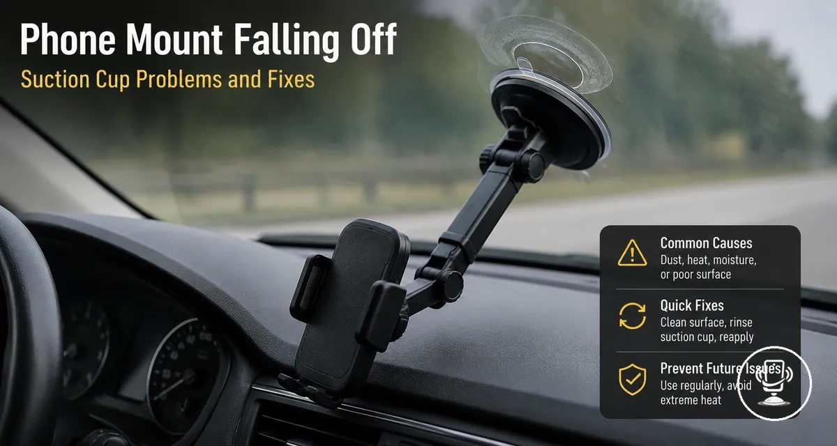
Vent clip slipping causes and basic fixes
Vent clip slipping usually comes from weak clip seating, unsuitable vent shape, excess phone load, loose vent fins, or mount angle leverage. These causes should be checked by separating vent clip gripping issues from actual vent movement before applying any basic fixes.
The diagnostic table below organizes vent clip slipping patterns into symptom, likely cause, basic fix, and when to stop using it. This helps distinguish whether the issue is coming from clip engagement or vent structure instability so that basic fixes stay safe and limited.
In some situations, vent clip slipping continues even after repositioning or reducing load. Repeated slipping or increasing wobble indicates that the vent support may no longer hold stable alignment, and in such cases it is important to stop using the mount to avoid further instability during driving.
| Symptom | Likely cause | Basic fix | When to stop using it |
|---|---|---|---|
| Repeated vent clip slipping on bumps | Weak clip seating or shallow engagement | Reposition clip for firmer contact on vent blade | Stop using if slipping continues after adjustment |
| Forward drop under phone load | Mount angle creating leverage | Adjust angle to reduce forward pull | Stop using if tilt returns immediately |
| Side wobble during driving turns | Unsuitable vent shape or spacing | Move to a more stable vent position | Stop using if wobble appears across multiple vents |
| Sudden shift or detachment | Loose vent fins or weak vent structure | Reduce phone load and recheck vent grip | Stop using if vent fins flex under light pressure |
| Progressive grip loss over time | Vibration loosening clip contact | Re-seat clip and check contact alignment | Stop using if grip weakens quickly after each reset |
:contentReference[oaicite:0]{index=0}
When the clip loses grip on the vent blade
When the clip loses grip on the vent blade, the issue comes from clip-level contact failure where the grip between the clip and vent blade weakens due to worn friction pads, shallow hook depth, blade thickness mismatch, dirty contact surfaces, or weak spring tension. This condition is different from vent movement problems, where instability comes from the vent structure itself rather than the clip-to-blade connection.
Before checking other factors, the focus should stay on whether the clip is maintaining direct contact with the vent blade. The checks below isolate grip loss at the clip level and help identify whether the problem comes from surface condition, hook engagement, or internal clip pressure.
- worn friction pads: cause is reduced pad surface grip; sign is slipping during light contact on the vent blade; cautious fix is cleaning and repositioning the clip to restore surface contact where possible.
- shallow hook depth: cause is limited engagement on the vent blade; sign is partial seating or easy detachment; cautious fix is adjusting placement to achieve deeper hook engagement if the vent blade allows it.
- blade thickness mismatch: cause is incompatibility between clip opening and vent blade size; sign is unstable hold or repeated dislodging; cautious fix is testing a more suitable vent blade position with compatible thickness.
- dirty contact surfaces: cause is dust or residue reducing friction; sign is weak grip even under light pressure; cautious fix is gently cleaning contact areas before reseating the clip.
- weak spring tension: cause is reduced internal clip pressure; sign is loose hold even after correct placement; cautious fix is checking alignment and avoiding forceful adjustment that could damage the clip mechanism.
:contentReference[oaicite:0]{index=0}
When the vent itself moves under phone weight
When the vent itself moves under phone weight, the vent moves as a support problem rather than a clip grip failure. The mount may stay clipped to the vent blade, but the vent fin or vent assembly shifts or flexes under load, which separates it from cases where the clip loses grip on the vent blade.
This type of vent movement usually increases when phone weight and long mount arms create leverage that creates downward sag over time. If vent moves repeat, using a more stable vent position or an alternative mounting location may reduce the load impact on the vent assembly.
- Loose fins: condition is flexible vent fins; symptom is visible fin movement under load; stability limit is reduced support and increased shifting.
- Lightweight vent assembly: condition is low structural rigidity; symptom is vent flexing under phone weight; stability limit is gradual position drift.
- Heavy phones: condition is high phone weight; symptom is increased downward sag; stability limit is overload on vent support.
- Long mount arms: condition is extended leverage distance; symptom is amplified movement at the vent; stability limit is wobble and downward sag.
Vent damage, blocked airflow, and safe use limits
Safe use of vent clip mounts depends on both mount fit and daily operating conditions, where vent stress, clip pressure, airflow direction, heat exposure, cold air, control access, and visibility all influence possible vent damage and blocked airflow. These effects do not mean vents will always be damaged, but they define safe use limits where stress conditions may increase risk depending on fit and usage context.
The risk checklist below organizes safe use limits by separating vent fin strength, airflow direction, device exposure, control access, and visibility into clear condition-based checks. This structure helps evaluate how clip pressure interacts with airflow direction and daily driving conditions, supporting safer decisions without assuming guaranteed outcomes.
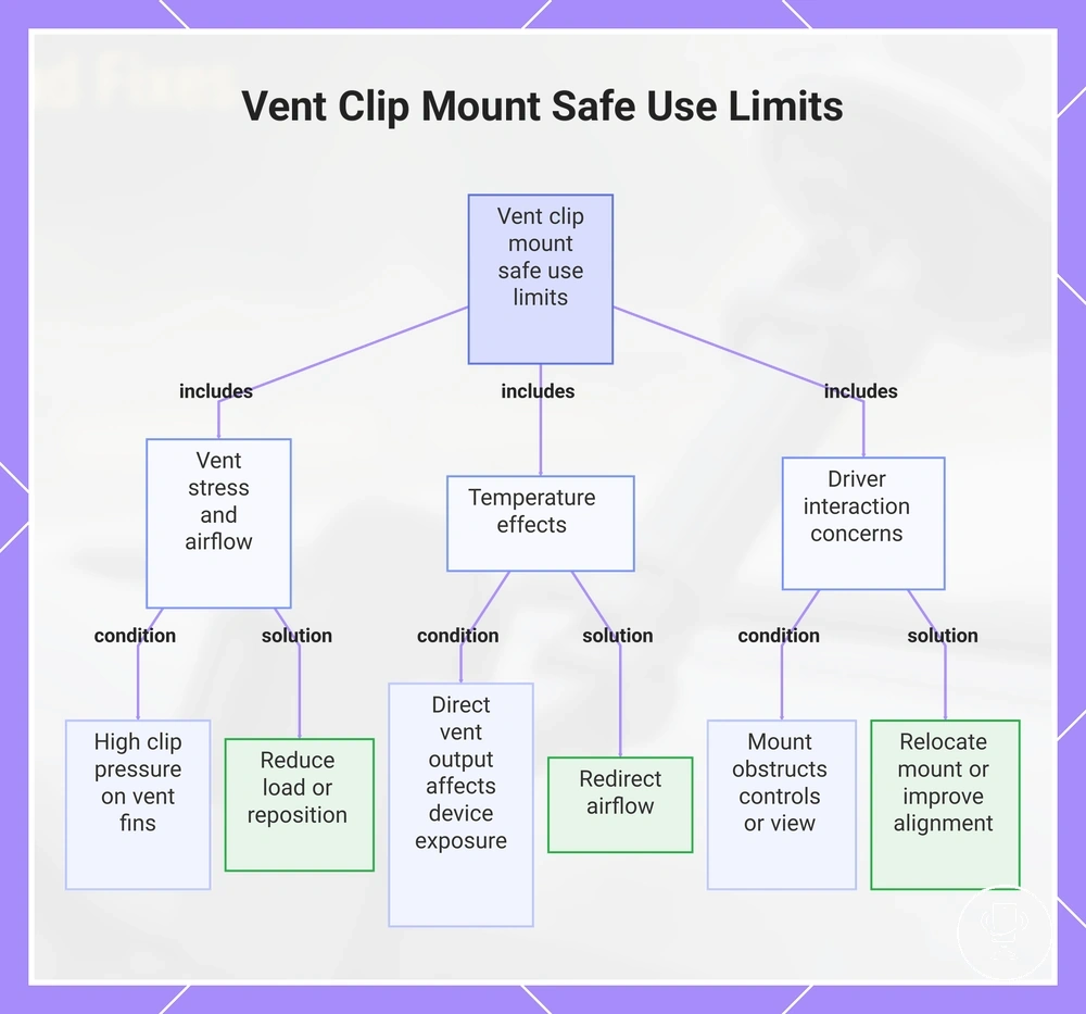
When vent stress increases, airflow becomes blocked, or heat exposure and cold air affect device positioning, the setup may exceed safe use limits. Reduced control access or visibility also indicates that repositioning may be needed to maintain practical use conditions. Safety here refers only to vent clip mount usage conditions and not broader legal positioning rules.
- Vent stress: high clip pressure on vent fins → visible flex or strain → safer decision is reducing load or repositioning
- Airflow direction: blocked airflow from mount placement → uneven cabin airflow → safer decision is adjusting mount position
- Heat exposure / cold air: direct vent output affects device exposure → temperature imbalance near phone → safer decision is redirecting airflow
- Control access: mount obstructs vehicle controls → reduced usability → safer decision is relocating mount
- Visibility: mount interferes with driver view → distraction risk → safer decision is improving placement alignment
:contentReference[oaicite:0]{index=0}
This chart groups the five risk factors for vent clip mount usage into three condition-based categories, showing each condition and its recommended safer decision.
When vent mounts can stress or break vent fins
Vent mounts can stress vent fins when clip pressure and phone leverage exceed the vent’s support capacity. In these conditions, vent fins experience stress that may lead to weakening or breakage risk, especially when brittle plastic, thin fins, or repeated repositioning reduce structural stability rather than causing guaranteed failure.
The risk increases when multiple load factors act together, and the warning signs usually appear before any actual break. The list below shows how specific conditions contribute to vent fin stress and what observable signals may indicate rising risk.
- Brittle plastic: condition is aged or rigid vent material → stress mechanism is concentrated clip pressure → warning sign is visible flexing or surface strain on vent fins.
- Thin fins: condition is low structural thickness → stress mechanism is amplified phone leverage load → warning sign is bending or gradual loosening under weight.
- Old vents: condition is worn vent structure → stress mechanism is reduced support strength under pressure → warning sign is instability during light movement.
- Heavy phones: condition is increased device weight → stress mechanism is stronger downward leverage → warning sign is progressive tilt or fin movement under load.
- Repeated repositioning: condition is frequent attachment changes → stress mechanism is contact wear on vent fins → warning sign is reduced grip consistency over time.
:contentReference[oaicite:0]{index=0}
How airflow and climate control affect daily use
Vent mounts can affect airflow and expose the phone to heated air or cooled air depending on vent position and climate control use in daily use. This interaction can influence airflow, climate control behavior, vent blockage, phone temperature exposure, passenger comfort, and control access depending on how the mount sits on the vent system.
Practical adjustment depends on how airflow and climate control are set during daily use and how the vent mount is positioned relative to direct air output. The impact varies with airflow direction, vent blockage, and phone temperature exposure, so adjustments are usually about balancing passenger comfort and control access within daily use conditions.
- Heating: heated air from climate control may increase phone temperature exposure when directed onto the mount, affecting passenger comfort during winter use conditions.
- Cooling: cooled air can flow directly onto the phone depending on vent angle, changing phone temperature exposure and airflow distribution during summer use conditions.
- Blocked airflow: vent blockage from the mount can reduce airflow efficiency, affecting passenger comfort and limiting effective climate control distribution during daily use.
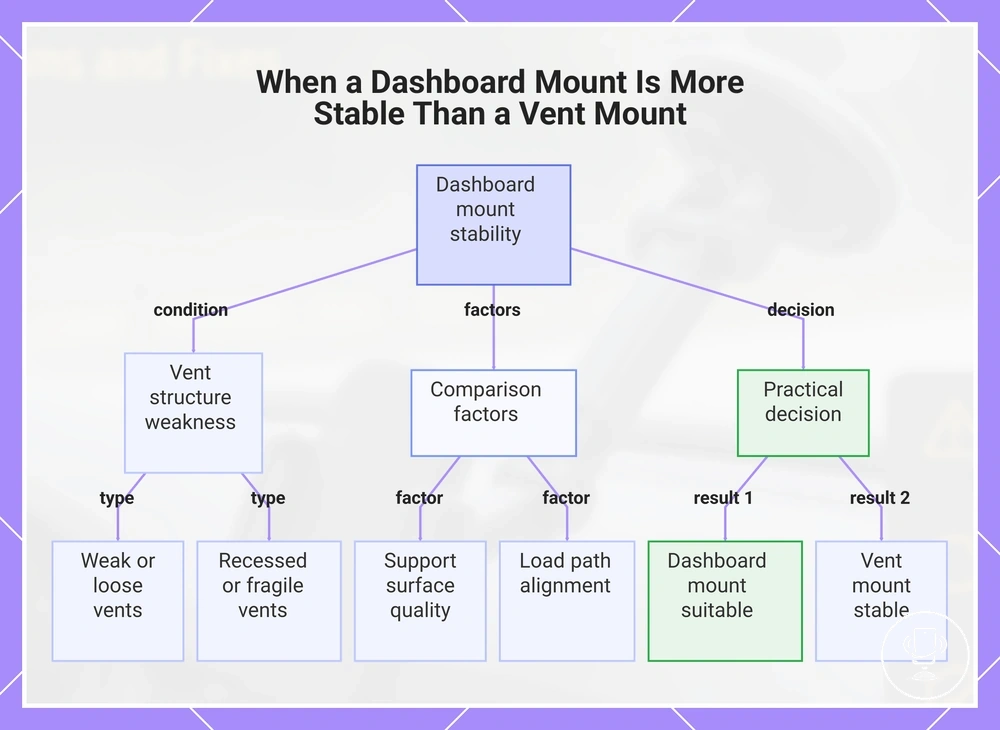
When a dashboard mount is more stable than a vent mount
A dashboard mount is usually more stable than a vent mount when the vent structure cannot provide consistent support under load. This is especially true when vents are weak, recessed, loose, or fragile, where the support surface and load path are not strong enough to hold phone weight steadily during daily use.
This comparison depends on support surface quality, load path alignment, visibility, and installation tolerance, which differ between vent mount and dashboard mount setups. For installation context, the dashboard installation guide explains how surface positioning can influence stability in daily use conditions.
In practical decision-making, a dashboard mount becomes more suitable when vent support is weak compared to cases where a vent mount can still hold a stable position. The broader differences between mounting options are explained in the mount type comparison, which helps evaluate the safer mounting path based on support conditions and load behavior.
The products below are useful examples for comparing available options. Before buying, check that the compatibility criteria, key features, and product details match your needs.
This chart shows the conditions under which a dashboard mount becomes more stable than a vent mount, the key factors affecting stability, and the practical decision based on vent support quality.