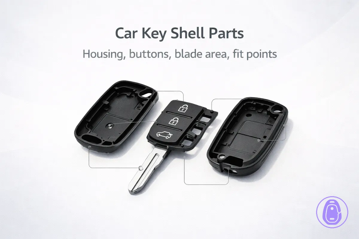
Car key shell parts: housing, button area, blade section, and fit points
Car key shell parts make up the outer casing you handle every day. They protect internal key fob electronics like the battery or circuit board. These parts can affect key assembly and handling. The key areas are housing, button area, blade section, and fit points.
Car key shells feature housing, button area, blade section, and fit points as core parts that support fit and daily use. The button area holds the button pad for function access. Fit points use clips and screws for secure closure. Deeper compatibility checks and replacement workflows are covered elsewhere.
- Housing: Main protective body.
- Button area: Surface with button pad for remote functions.
- Blade section: Insertion part with slot and pivot.
- Fit points: clips, screws for assembly.
Car key shell parts versus the internals inside a key fob
Shell parts form the outer casing and interface pieces of a key fob. They make up its external shape and the spots you touch, like buttons. These protect internals without holding electronic functions. Opening the shell reveals internals, but this page names parts rather than teaching replacement.
Key fob internals—like the circuit board and battery—typically manage signal transmission and power. Buyers often mistake an empty shell for a complete remote key assembly because the shell lacks internals.
Shell parts
- Outer casing, the main plastic housing
- Button pad, the rubber part for button presses
- Key blade holder or key blade slot interface
- Battery compartment cover
- Flip mechanism housing, if present
- Button covers or trim pieces
Not shell parts
- Internals (electronic modules)
- Circuit board, typically controls remote functions
- Battery, supplies power
- Antenna, typically for signal transmission
- Transponder chip, often for vehicle matching
This flowchart defines car key shell parts, lists key included components, and shows excluded internals for clear distinction.

Outer shell parts versus internal electronics, battery, and the metal key blade
The car key shell is the outer housing around the internal electronics, battery, and transponder. An "empty shell" is not a complete key, so confusing the two often leads to purchase errors—shells typically lack these internals.
| Shell parts | Non-shell parts |
|---|---|
| Plastic housing | Electronics module |
| Button covers | Circuit board |
| Flip mechanism casing | Battery |
| Keyring attachment | Transponder |
| Blade retention slot | Key blade |
Common part names used in listings and repair instructions
Listings and repair instructions often use different terms for the same physical parts. Terms like case, cover, and shell vary across sellers. Here’s how names map to parts.
- Shell case → often the complete outer housing
- Housing halves or casing → often the two main plastic pieces that form the shell
- Button pad → often the rubber piece with raised buttons inside the shell
- Membrane → often the thin layer over the button pad that protects it
- Blade slot → often the opening where the key blade slides in
- Hinge or pivot → often the pivot point for flip-style shells
- Clips or tabs → often plastic tabs that snap housing halves together
- Screws → often metal fasteners holding some shells closed
- Keyring loop → often the ring hole at the shell end for attachments
This flowchart maps common terms from listings and repair instructions to the physical parts they describe on key fob shells.

Housing body parts that form the shell shape
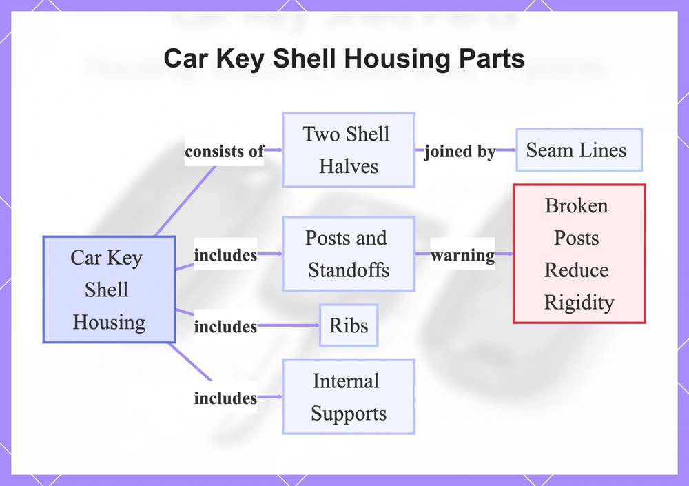
The housing forms the primary structure of the car key shell. It consists of two shell halves that join along a seam to create the outer shell. The housing provides the structural frame for other shell parts.
Proper alignment of the housing halves ensures good closure and shell rigidity. Seam lines between the halves distribute stress, which may reduce flexing during daily use. Internal features like posts and ribs enhance the housing's stability.
- Housing halves: Panels joined along the seam.
- Seam lines: Joining edges for tight alignment and closure.
- Posts and standoffs: Protrusions that secure components and add rigidity.
- Ribs: Reinforcing ridges that improve strength.
- Internal supports: Frames guiding alignment and preventing shifting.
Seam tightness varies across models. Broken posts can lead to poor alignment and reduced rigidity in the shell halves.
This flowchart shows the main components forming the car key shell housing, their connections, and a key rigidity risk.
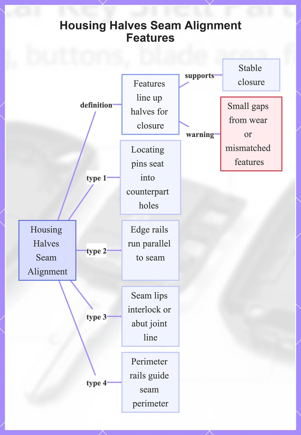
Housing halves and seam alignment areas
The housing halves meet along a seam where alignment features line them up for closure.
These features support a stable closure, though small gaps can appear from wear or mismatched features. Common alignment features include:
- Locating pins that seat into counterpart holes for positioning
- Edge rails that run parallel to the seam for edge alignment
- Seam lips that interlock or abut to define the joint line
- Perimeter rails that guide the seam perimeter
- Alignment notches that help prevent twisting
- Recessed guides for pins or rails
This flowchart explains seam alignment areas where housing halves meet, their role in stable closure, potential gaps, and common feature types.
Internal posts, standoffs, and support ribs inside the housing
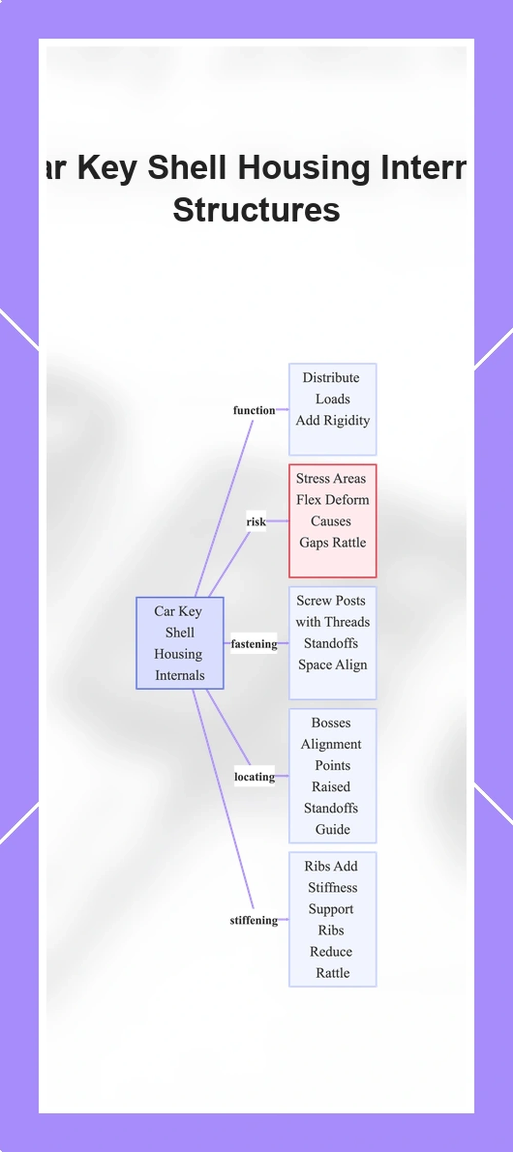
Inside the housing of a car key shell, plastic internal structures such as screw posts, standoffs, bosses, and ribs support the shell and hold shell interfaces in place. They distribute loads and add rigidity without electronics. Stress areas around these elements can cause closure gaps or rattle if they flex or deform over time.
Fastening features:
- Screw posts have molded threads to secure halves with fasteners, but overtightening can strip them.
- Standoffs space shell halves correctly and align fasteners.
- Internal frame elements reinforce screw post bases against torque.
Locating features:
- Bosses act as alignment points for shell halves.
- Raised standoffs guide shell halves and prevent shifting.
Stiffening features:
- Ribs add stiffness to reduce flex in high-stress zones near hinges.
- Support ribs connect bosses to walls and minimize rattle from vibrations.
- Thicker rib sections target areas prone to deformation and closure issues.
This flowchart categorizes the plastic internal structures in car key shell housings by type, explains their support functions, and highlights stress-related risks.
Button area parts that create the press feel and alignment
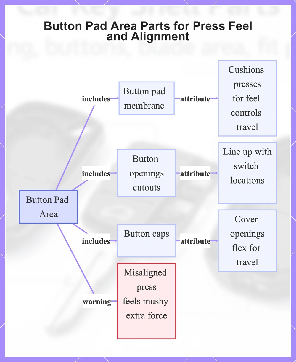
The button pad area in a car key shell has parts that shape press feel, travel, and alignment with internal switch contact points. The button pad or membrane compresses for tactile feedback and sets button travel distance. Button openings and button caps line up the buttons over switch points. Alignment features hold these parts in place.
- Button pad/membrane: Cushions presses for feel and controls travel.
- Button openings or cutouts: Line up with internal switch locations.
- Button caps: Cover openings and flex for travel.
- Button surround: Keeps caps from shifting.
- Alignment features: Like pins or rests that position parts.
- Press-fit elements: Lock components to reduce play.
A misaligned press can feel mushy or take extra force without crisp response. For instance, worn alignment lets button caps shift, so the press sinks unevenly and may miss the switch. Such problems can stem from mechanical offset in the button pad area.
This flowchart details the main parts in a car key shell's button pad area, their roles in press feel, travel, and switch alignment, plus a key risk.
Button pad or membrane placement and how it seats in the shell
The button pad or membrane sits flat in the shell recess, its perimeter aligned beneath button openings so presses reach underlying contacts. Locating tabs on the pad fit into shell channels to set orientation and resist rotation. Compression points along the edges secure the pad, typically without distorting internal domes or circuits. Pinch zones near the tail exit may hinder shell closure if the pad bunches or shifts.
Seating cues help identification; full transfer steps belong elsewhere.
- Locating tabs fit into shell channels.
- Pad lies flat under button areas.
- Perimeter edges compress.
- Tail routes through designated slot.
- No bunching in pinch zones near edges.
- Domes retain shape without inversion.
Button caps, openings, and travel clearance in the housing
Openings in the housing shape the path for button caps to move when pressed, supporting smooth travel without binding. Clearance around the cap shape and edges avoids contact with housing walls for easy vertical or lateral motion.
Burrs on edges or housing deformation can shrink clearance and cause binding, where the cap sticks during presses. Opening alignment with cap shape ensures steady travel.
- Opening geometry matched to cap dimensions directs motion without excess side play.
- Smooth chamfers or radii on edges cut down scraping on cap surfaces.
- Cap shape sets clearance needs, as rounded or tapered forms lower binding risk.
- Travel space with clearance past full cap excursion on all sides supports reliable action.
Blade section parts for flip and non-flip key shells
Blade section parts handle the interface where the key blade connects to the shell housing. The blade slot guides blade insertion, while retention features like roll pins hold the blade steady. These parts manage blade play and stability, with tighter retention reducing wobble.
Flip key shells include a hinge and pivot area near the blade section to enable folding, unlike non-flip shells. Non-flip shells lack the hinge and rely on fixed blade housing for stability. Such design differences can affect play, as flip models may develop pivot movement from wear.
- Flip key: Includes hinge and pivot for blade rotation, with retention typically via roll pin in the blade slot.
- Non-flip: Relies on fixed blade slot and retention for stability, without pivot or folding.
Detailed blade-and-hinge matching for specific models is handled in the Compatibility hub.
Blade slot geometry and retention features in the shell
Blade slot geometry and retention features keep the blade stable within the shell. The slot shape, stop surfaces, retention clips, and channels resist movement in multiple directions. Slot geometry such as tapers and cross-sections behind the edge influences blade seating. Wear often occurs at these contact points. Such wear can introduce wobble or blade play.
- Slot shape matches blade cross-section for initial fit.
- Stop surfaces form flat or angled barriers against sliding.
- Retention clips engage blade notches or edges.
- Channels guide blade fullers or ridges for alignment.
- High-friction interfaces at stop surfaces, retention clips, and channels wear over time.
Hinge or pivot parts in flip-style shells and where the wear happens
The hinge or pivot area forms the mechanical connection between flip sections in the shell. It enables smooth opening and closing. Core parts include the pivot seat, hinge barrel, and stop surfaces. These guide rotation and limit motion.
Tight tolerances that vary by design can loosen over time from wear. This introduces play between components. Friction builds at contact points like the pivot seat and hinge barrel during repeated use.
- Pivot seat: Holds the rotating pin or axis, which can wear from side loads.
- Hinge barrel: Encircles the pivot, where friction can erode surfaces over cycles.
- Stop surfaces: Prevent over-rotation, which can develop play from repeated impacts.
A loose hinge or pivot often feels like uneven resistance or subtle grinding during flips. You may notice extra movement between shell halves from friction and play buildup. This does not involve internal spring or lock parts.
Closures and fasteners that keep the shell closed
Closures and fasteners such as clips and screws secure the housing halves of the car key shell. Clips have tabs that snap into latch points to hold the halves together and maintain alignment. Screws thread into screw posts to reinforce the closure and prevent separation. Without effective closure, gaps may develop or the shell may pop open.
Clip-based closure
- Tabs flex to fit into latch points for quick engagement.
- Provide snap-fit alignment for repeated access.
- Distribute force evenly across multiple latch points.
Screw-based closure
- Screws thread directly into screw posts at key locations.
- Enable tension adjustment for alignment.
- Positioned along edges to counter flexing forces.
- Provide mechanical locking.
Excessive force during handling can harm these closures, such as forcing clips past latch points or overtightening screws into screw posts. For instance, overtightening screws may strip the screw posts, which can lead to gaps or the shell popping open, as explained in Replacement mistakes to avoid.
Clip closures, tabs, and where they usually break
Clip closures work as tab-and-slot interfaces. They hold the car key shell under tension by snapping tabs into matching slots. Tabs usually feature hooked ends for solid engagement with the slots. Engagement depth determines how securely the tabs seat and distribute tension across the shell halves.
Tabs commonly show stress whitening from repeated flexing or snapped hooks at the base.
- Perimeter edges where shell halves join
- Battery compartment access tabs
- Button module retaining slots
- Side seam snap tabs
- Rear panel clip points
- Internal rib engagement areas
Screws and screw-posts inside the housing and why they strip
Screws engage threads in screw-posts (also called plastic posts or screw bosses), molded inside the compact housing of a car key shell to ensure closure and alignment.
Stripping happens at the screw-post interface when threads lose grip, often from overtightening that deforms soft plastic or cross-threading that damages mating surfaces. In tight housings, limited thread engagement makes it worse, as screws set with minimal purchase before bottoming out.
- Overtightening: Excess force can crush plastic threads, causing stripping and post cracking.
- Cross-threading: Misaligned entry can mangle threads, causing poor engagement and stripping.
- Insufficient thread engagement: Short screws or deep posts reduce contact area, promoting stripping under torque.
- Post cracking: Plastic can fracture from repeated stress, allowing screws to spin freely.
Hidden screw locations and release notches used with clip closures
Hidden screws are common fasteners in shell closure designs with clip closures, maintaining a seamless appearance. Hidden screws often sit beneath covers or within recesses along the edges or base of the shell. Release notches are subtle indentations or thinned areas near seams where tabs engage. Forcing the wrong seam can damage tabs and hinder reassembly.
- A small circular recess under covers that signals a hidden screw.
- A thin slot or groove parallel to the seam that indicates a release notch.
- Notched edge on tabs within the seam.
- Slight depression or dimple near fastener points.
- Overlapping seam with tapered release notch.
- Concealed screw head aligned with clip tab positions.
Fit points on the shell that determine whether parts line up
Fit points serve as alignment and registration features on the car key shell. They control closure quality along with button alignment and blade alignment. Locating features within fit points help internal components seat correctly and cut down on interference during assembly. Fit points feature specific outline contours that guide seating and prevent misalignment. Mismatched fit points can cause poor closure or functional problems, depending on the design.
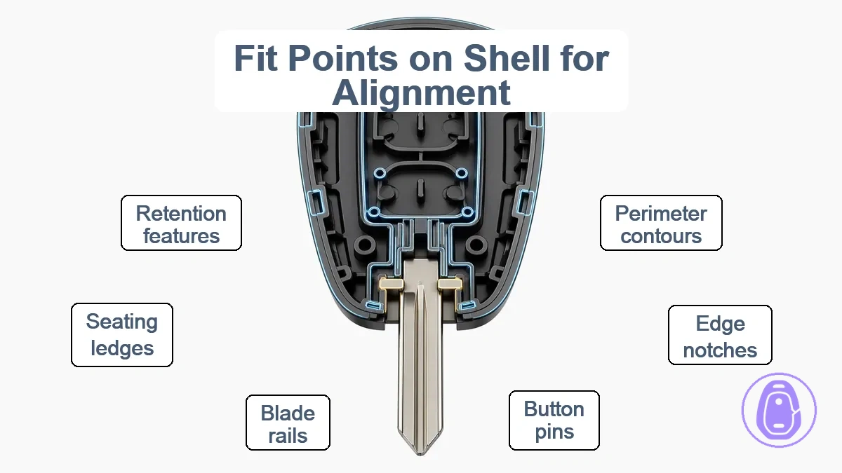
A cosmetically similar outline might seem compatible at first. But a functional match needs the locating features and registration to align properly and reduce interference. Button alignment hinges on matching registration points, and blade alignment requires corresponding seating surfaces. Visual checks alone often miss subtle differences in these features.
Check multiple fit points across different areas before picking a replacement shell—similarity at one point doesn't confirm overall fit. For deeper verification, visit the Compatibility hub.
Visual similarity alone is not enough.
Fit points by area
- Outline:
- Perimeter contours for initial seating.
- Edge registration notches.
- Interference ledges that control depth.
- Button area:
- Button registration pins or slots.
- Surrounding walls for button alignment.
- Interference stops for button travel.
- Blade area:
- Blade channel alignment rails.
- Seating ledges for blade base.
- Retention features designed to minimize interference.
- Sidewall registration for blade centering.
Common fit-point misses
- Overlooking outline interference points, which may lead to uneven closure.
- Assuming button area similarity ensures alignment.
- Ignoring blade area registration, which may cause wobble.
External outline and locating features that control seating
The external outline of a car key shell controls how well the halves seat together without gaps. Locating rails and pins along this outline guide the halves into proper alignment. Shells with a similar shape often fail to seat properly when perimeter variations or small differences in rail height, pin placement, or outline profile arise. Visual comparison of these features uncovers compatibility issues.
- Continuous perimeter outline without steps or offsets
- Locating rails matching in position and depth along edges
- Pins or tabs aligning symmetrically on opposing halves
- Consistent spacing between multiple locating rails
- Smooth transitions in outer contour without protrusions
- No redundant features interfering with seating
Button area registration features that control button alignment
Registration features position the button pad within the button pad area to align buttons with shell openings, so presses land correctly. They maintain spacing and centering between the button pad and the shell openings above. Without these features, small shifts can lead to off-center presses.
- Tabs that slot into corresponding receivers on the shell to prevent lateral movement of the button pad.
- Channels that guide the edges of the button pad for repeatable positioning and spacing.
- Posts, or locating posts, that center the button pad by fitting into matched holes.
- Alignment tabs that provide rotational stability and spacing control.
- Interlocking channels that maintain vertical centering relative to button openings.
Blade section alignment surfaces that control blade fit and play
Alignment surfaces in the blade section—stop surfaces, shoulders, pivot seats, and seating surfaces—serve as contact points. They stabilize the blade against the shell interface and minimize blade play. Mismatch between blade and shell alignment surfaces often causes looseness, where the blade shifts under pressure. It can also lead to poor closure if contact points do not align properly.
- Stop surfaces: Flat areas that limit forward or backward blade movement and reduce play at the ends.
- Shoulders: Raised edges that center the blade laterally and limit side-to-side looseness.
- Pivot seats: Curved or notched areas that support rotational fit and maintain stability under torque.
- Seating surfaces: Broader contact zones that improve blade-to-shell contact and prevent minor shifts.
External attachment parts like the keyring loop and lanyard points
Car key shells rely on the keyring loop and lanyard points as load-bearing attachment parts for keychains or lanyards during daily carry. The keyring loop usually takes a circular or oval shape that lets a split ring pass through. Lanyard points typically consist of slots or reinforced eyelets nearby.
- Simple loop: Basic ring hole molded into the shell edge.
- Slot design: Narrow opening for strap threading.
- Reinforced eyelet: Thickened rim around the hole.
Yanking the keyring loop to pull keys from a pocket creates stress at the attachment. This stress can transfer to nearby housing areas and lead to cracks over time. Repeated tugs during daily carry raise break risk, as the housing flexes and fatigues early near these points.
Keyring loop design and stress points from daily carry
Keyring loop designs commonly use circular or double-loop shapes. These expose stress points during daily carry. Stress points often include a thin neck or sharp corners that act as stress risers where force builds up.
Attached keychains create leverage that multiplies the load on the loop design and transfers it to adjacent housing material. Flex in these areas can signal potential weak points that may lead to cracks over time.
- Thin neck: A narrow section between loop and housing prone to bending under leverage.
- Sharp corners: Edges that concentrate stress and promote flex during repeated use.
- Flex: Visible deformation from keychain weight that can indicate fatigue risk.
How to identify shell parts and fit-critical features before ordering a replacement shell
Outline your existing key shell's external shape, button layout, and blade section to identify parts and fit-critical features. Compare them to potential replacements using multiple cues to cut mismatch risk—a single photo often misses dimensions and angles. Use this checklist.
- Note the overall outline and dimensions of the shell exterior.
- Look at the button layout, including number, shape, and spacing of buttons.
- Check the blade section profile, noting length, width, and cutouts or notches.
- Note positions of screws/clips or mounting points visible externally.
- Compare edge alignments and visible frame cutouts.
- Check for part numbers or markings on the shell surface.
- Note material texture and thickness around button and blade areas.
- Check fit-critical points like button recesses and blade channel dimensions.
After checking fit with this checklist, handle replacement actions in the Replacement hub.
What you can confirm from the outside without opening the shell
Outside cues like outline, button spacing, blade area, seam, screw points, and attachment points provide visual match points when comparing car key shells. These observable features can suggest similarity across models but come with uncertainty from manufacturing variations or hidden internals. Compare these areas side by side with your original shell to narrow options.
Outside cues narrow options; they don’t prove fit.
Outline
- Profile shape and overall contour may align.
- Seam locations around edges can show consistent placement patterns.
- Visible screw points suggest similar external mounting.
Buttons
- Button spacing and arrangement may match.
- Button size and shape can match visually.
Blade area
- Visible blade interface cues like slot shape or notch position can indicate potential alignment.
Attachment points
- Exposed clips or tabs around edges suggest comparable connection styles.
For broader guidance, Back to Car key shell hub.
What to check after opening the shell without turning it into a replacement guide
After opening the car key shell, compare inside cues like the internal post layout and screw-post positions for alignment. The pad seating and blade-area interface should match. Handle internals carefully, since they may be sensitive. This is what to look at, not how to swap parts.
- Internal post layout typically aligns evenly without gaps or offsets.
- Screw-post positions typically match in number and spacing.
- Pad seating features typically sit flush against designated areas.
- Blade-area interface typically shows consistent contour fit.
- Typically, no visible stress marks near screw-post positions.
- Pad seating depth typically corresponds to original contours.