Car Key Shell Internal Transfer Without Damage
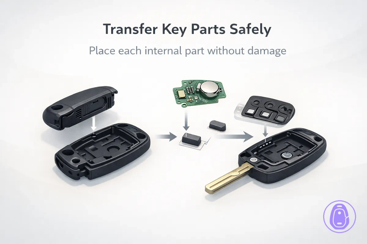
Car key shell internal transfer means taking the internals out of your old shell and moving them to a new Car key shell—also called a key fob shell. These internals usually include the circuit board, battery contacts, button pad, and sometimes a transponder chip.
Success depends on the circuit board and button pad sitting flat and aligning with the button holes. This page focuses on safe physical transfer only, not full replacement steps or problem diagnosis.
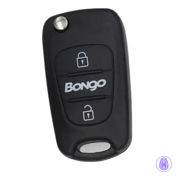
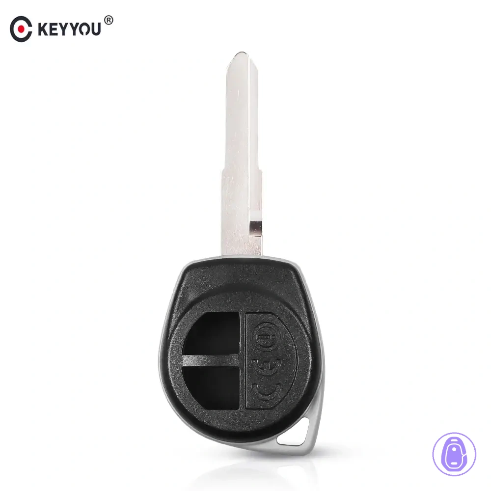
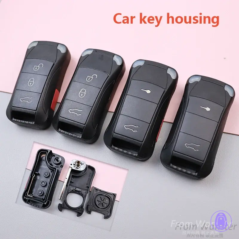
Gentle handling without force or twisting sets the right mindset for transferring Car key shell internals. Buttons often fail to work from misalignment, or the shell won't close due to poor seating. The fix is usually to reopen and reseat. Back to replacement hub.
Shell designs may use clips or screws, affecting how you open and reassemble them.
- What transfers: circuit board, battery contacts, button pad, transponder if present.
- Risks: buttons not working from misalignment, won’t close from lift points.
- Core rule: alignment-first so internals sit flat against posts and channels.
If anything resists closure, stop and reseat—don’t force it.
Internal components involved in a Car key shell swap and why they matter
Internal components transferred during a Car key shell swap typically include the circuit board or PCB, battery and contacts, button pad or membrane, and inserts or spacers.
The circuit board handles signals for remote functions. The battery delivers power through its contacts. Misaligned battery contacts often cause intermittent power. The button pad pushes against the circuit board through button holes for responsive buttons. Poor alignment can make buttons unresponsive. Inserts and spacers maintain alignment for proper fit and closure. Keep parts oriented to avoid problems.
- Circuit board and battery: handles signals and supplies power; mis-seated can cause intermittent operation or no response.
- Battery contacts: hold the power connection; bent or misaligned contacts can cause intermittent power.
- Button pad or membrane: actuates buttons via button holes; mis-seated often causes buttons not working.
- Inserts or spacers: support alignment and fit; improper seating can prevent closure or cause looseness.
- Electronics module alignment: keeps parts sitting flat; offset positioning disrupts button response and closure.
People often think shell swapping needs reprogramming, but shell swap changes the housing; it doesn’t change your key’s electronics identity. This page covers physical transfer only.
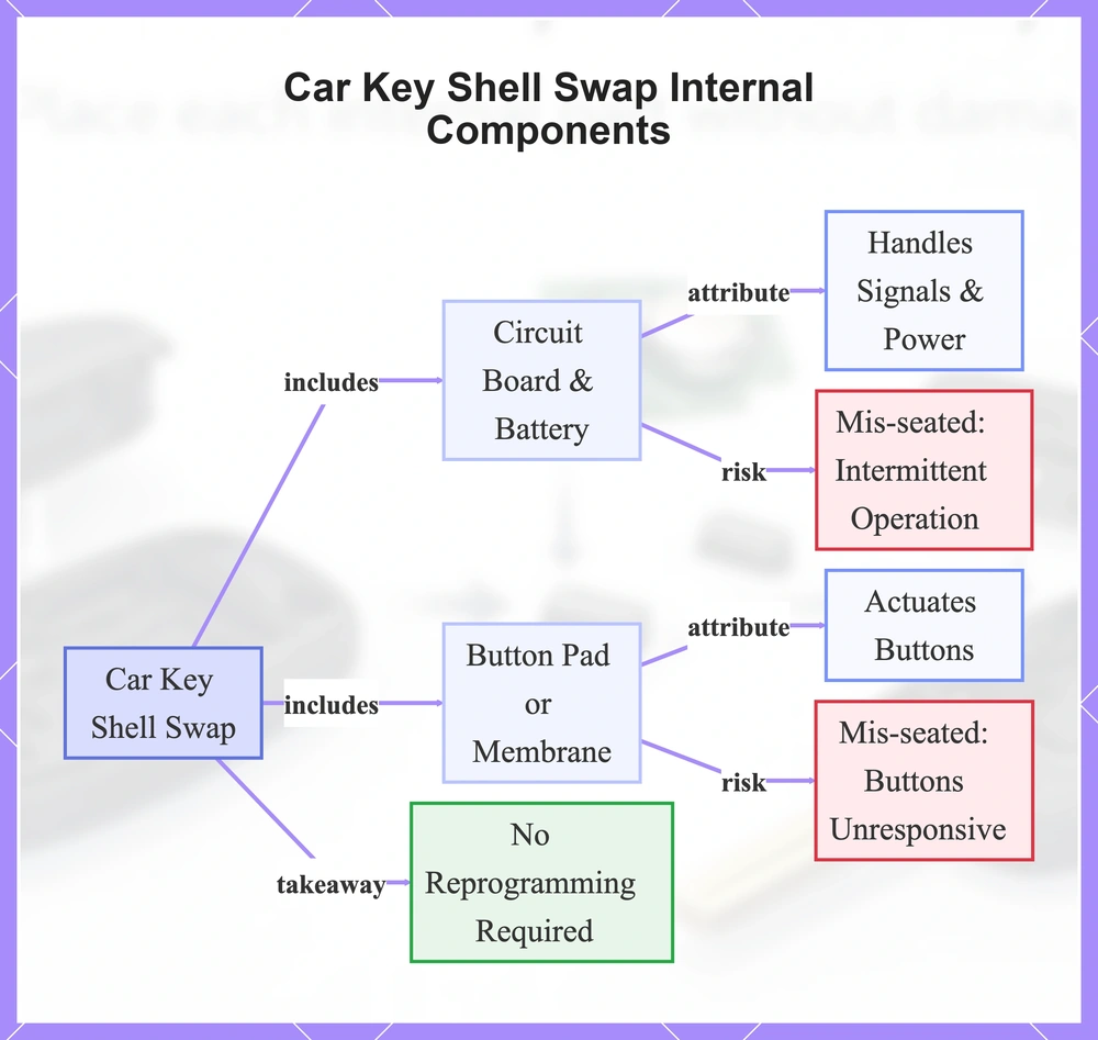
This flowchart shows the key internal components transferred during a car key shell swap, their roles, common misalignment risks, and that no reprogramming is required.
Circuit board, battery contact points, and how button presses are registered
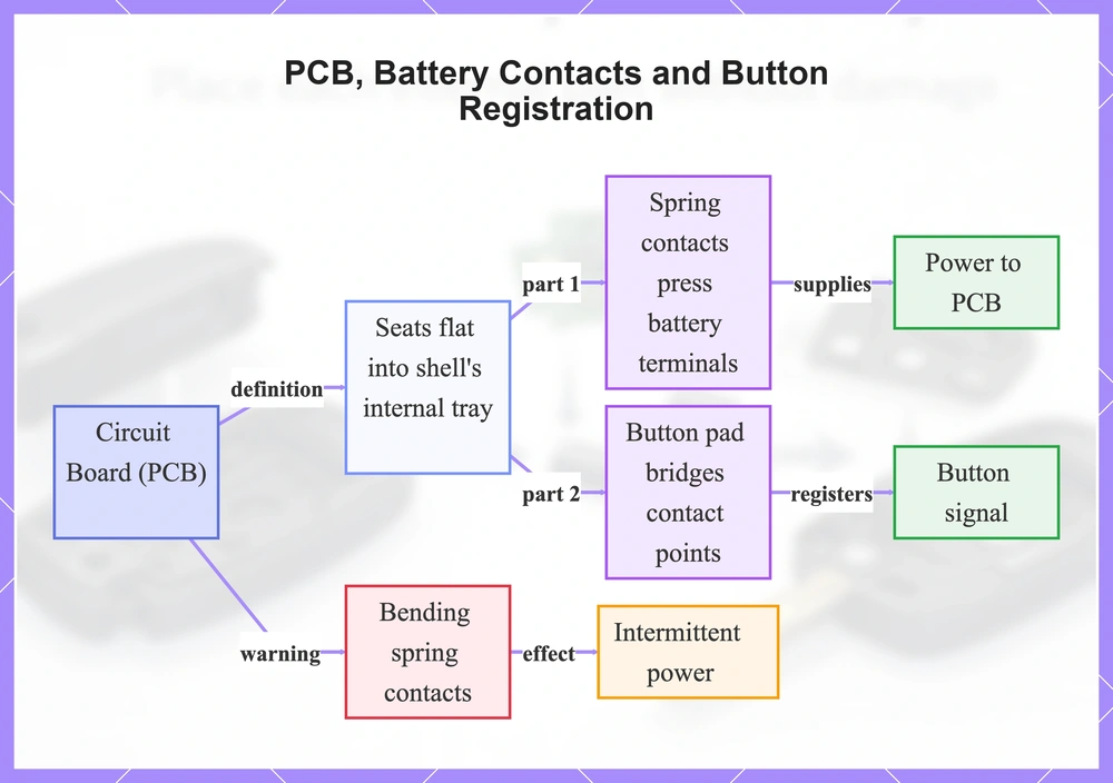
The circuit board, or PCB, seats flat into the shell's internal tray. It aligns with battery contacts and button contact points for electrical connections. Battery contacts—often spring contacts—press against battery terminals to supply power to the PCB. A button press happens when the button pad bridges button contact points on the PCB, registering the signal. Bending spring contacts is a common mistake that can cause intermittent power. Don’t press on components.
A board that rocks or sits above the tray isn’t seated.
- Hold the PCB by its edges to avoid stressing contacts.
- Avoid bending spring contacts.
- Confirm spring contacts touch battery terminals evenly.
- Not-seated PCBs show edge gaps or button contact misalignment.
This flowchart explains PCB seating in the shell, battery and button electrical connections, signal registration process, and a common mistake with its effect.
Immobilizer chip or transponder placement and what happens if it is missed
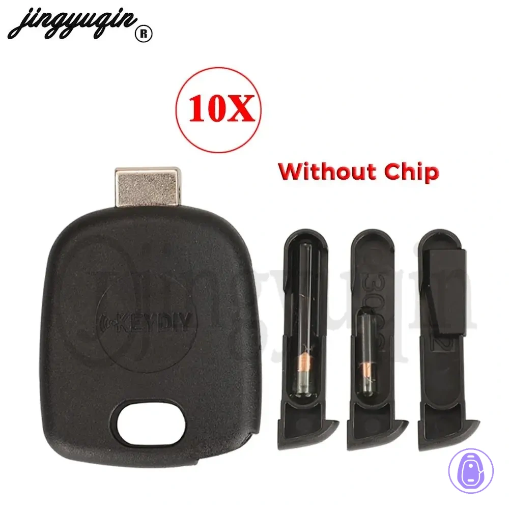
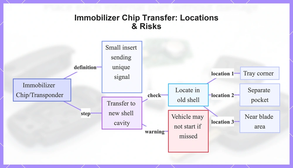
Some car keys include a separate immobilizer chip or transponder as a small insert. Transfer it to the new shell when present. The transponder fits into a cavity in the shell and sends a unique signal to your vehicle's immobilizer system. Miss the chip during transfer, and the vehicle may not recognize the key or start.
Locate and move just the chip—no programming needed here. Can't find it? Pause, check the old shell again, and avoid forcing the shell closed until you confirm the transponder is in place.
- Tray corner
- Separate pocket
- Near blade area
This flowchart shows the immobilizer chip in key shells, transfer process, where to locate it, and risks if missed.
Confirm the new shell will accept your internals before you start the transfer
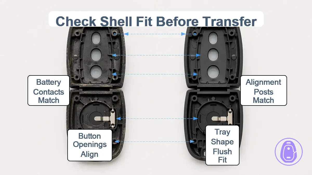
Before moving internals from the old shell, confirm the new shell's compatibility to accept them.
Verify alignment posts match, tray shape lets internals sit flush, button openings line up with the button pad shape, and battery contact geometry aligns properly. These points help internals seat right without issues. Housing geometry mismatches can block a good fit. Never force closure on a failed check.
Such mismatches commonly cause dead buttons due to poor button pad contact or a shell that won’t close from raised internals. Halt the transfer, line up old and new shells for comparison, then reseat after alignment checks. A fast pre-check like this cuts wasted effort and risk. Persistent problems mean checking compatibility again first.
| Must-match point | What to look for | What goes wrong if off |
|---|---|---|
| Alignment posts | Posts line up with internal holes | Internals may shift, fail to sit flush |
| Tray shape | Shape cradles board evenly | May create lift points blocking closure |
| Button openings vs pad shape | Openings match pad outline | Buttons may become unresponsive or stuck |
| Battery contact geometry | Contacts align without overlap | May cause intermittent power or no response |
Q: Do I need to reprogram after swapping shells?
A: Usually no—you're just moving the same electronics. Problems tend to stem from seating or chip transfer, not programming. Shell swaps rarely need reprogramming.
Button holes, rubber button pad shape, and alignment posts that must match
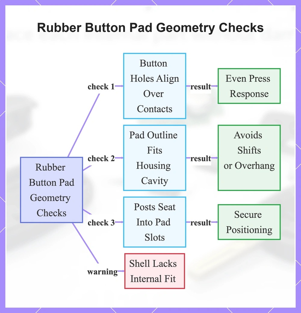
Key geometry checks on the rubber button pad include button holes alignment, pad outline fit, and posts positioning. Button holes align over the rubber button pad's raised contact points so presses transmit responsively to the circuit board. The rubber button pad outline fits the housing cavity to avoid shifts or overhang during closure. Alignment posts, or locating posts, seat into pad slots for secure positioning.
If the pad cannot sit flat and align cleanly, the shell lacks internal fit.
- Pass if button holes line up over pad contact points for even press response; fail if offset leads to dead or sticky buttons.
- Pass if pad outline seats fully within housing edges; fail if overhang or gaps prevent flat seating.
- Pass if posts engage pad slots without force; fail if mismatch causes rocking or incomplete alignment.
This flowchart shows the key geometry checks for the rubber button pad, their pass results, and the main failure outcome.
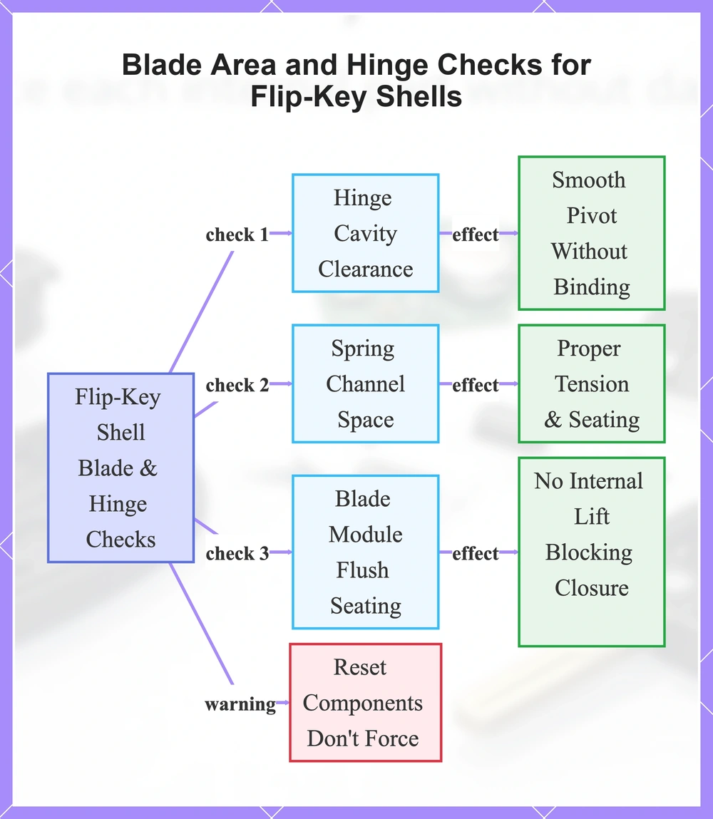
Blade area and hinge region checks for flip-key shells without turning this into a fit guide
For flip-key shells, check hinge cavity clearance, spring channel space, and blade module flush seating before internal transfer.
Hinge cavity clearance supports pivot movement without stress. Spring channel space handles tension for smooth action. Flush seating prevents internal lift that blocks closure. These features may vary by design, so mismatches hinder reassembly. Reset components rather than forcing them.
- Hinge cavity clearance for smooth pivot without binding internals.
- Spring channel space for proper tension and seating.
- Blade module sits flush with no lift affecting closure.
This flowchart outlines essential pre-transfer checks for flip-key shell hinge cavity, spring channel, and blade module, including their effects and reassembly warnings.
Preparation that prevents lost parts, cracked housings, and contact damage
Setting up to transfer internals into a new car key shell requires a controlled workspace to cut risks of losing small parts or damaging components from forced reassembly. Good lighting in a dedicated area helps handle clips and posts carefully while avoiding force on delicate electronics. Small parts control sets up the whole process for success.
Poor preparation often causes lost springs or chips that make reassembly tough, or pinched pads that ruin button function after closure. Skipping orientation tracking with photos or layout notes can lead to incorrect reassembly that stresses housings until they crack. Pause before closing to check that small parts like springs and chips sit right in containers.
- Choose a light, clean surface free of clutter.
- Use a small container to capture springs, chips, and other small parts.
- Note the orientation of internals with a quick photo before disassembly.
- Keep old shell halves separated to maintain layout during transfer.
- Group screws by their original positions in a marked container.
- Verify clips and posts remain undamaged before proceeding.
- Avoid force by double-checking part placement at each stage.
This flowchart shows the key preparation steps and checks to prevent lost parts, cracked housings, and contact damage during internals transfer.

Workspace setup and small-part control for springs, chips, and screws
When disassembling a flip-key car key shell, isolate spring parts first to prevent loss during the transfer. Set up a clean, well-lit workspace with small containers nearby to track orientation and location of parts like springs, screws, and inserts. Use one container per group.
- Label orientation of each half with a marker or photo.
- Separate shell halves completely and place them side by side.
- Isolate springs immediately into a dedicated container.
- Isolate inserts and chips to avoid mixing with other parts.
- Group screws by location using separate containers.
- Photograph the layout before moving any internals.
- Check all containers against the old shell for completeness.
Handling precautions for electronics and battery terminals during disassembly
Grip electronics and battery terminals by safe edges to cut damage risk when removing them from the old car key shell. Avoid prying under components, since that can deform terminals or contacts and cause poor connections.
Guard battery contacts against more deformation, bending, or shorting exposure. Deformed contacts can trigger intermittent power issues that disrupt button response after reassembly.
Do
- Lift components by safe edges.
- Inspect contacts before handling to check their shape.
- Keep one hand clear of conductive paths.
Avoid
- Prying directly under components or boards.
- Deforming or bending terminals and contacts.
- Shorting contact areas with tools or metal objects.
Opening the old shell and the new shell without snapping clips or posts
The split line shows where the car key shell halves meet, usually along the edges or back. Check for clips around the perimeter or visible screws holding the halves. Find a pry point right on the split line to begin. Apply even pressure along the perimeter to free the clips without stressing posts.
Twisting the halves or forcing one spot can break clips or bend posts, making reassembly tough. Go around the perimeter steadily instead.
Loosen any screws first, then re-seat them later for proper alignment. When it sticks, check what's holding the halves before forcing it. If you need the full replacement flow, see Replacement steps.
- Identify the split line or seam.
- Loosen screws evenly.
- Separate evenly at the pry point.
- Stop if bending or stress appears.
- Set halves aside separately.
Clip-release approach that avoids twisting force and stress whitening
Twisting force or single-point prying can create excessive flex that bends the housing or leads to stress whitening where clips meet the perimeter. A distributed clip-release approach works the perimeter with minimal flex to separate halves evenly and reduce localized stress. If the housing bends or stress whitening appears, stop and change the leverage point.
- Begin at a pry point and progress steadily around the perimeter.
- Apply light, even pressure to successive clips without concentrating force.
- Monitor for flex as you circle back to the starting point.
Screw-based shells and where overtightening later usually causes closure issues
Uneven screw seating and overtightening can warp the shell halves, creating gaps along the seam.
Overtightening puts too much stress on the plastic housing. This often causes misalignment where the halves won't meet evenly.
A corner gap after tightening signals this warping.
- Tighten screws evenly across all points.
- Alternate sides to keep balance.
- Stop when screws sit snug.
- Recheck the seam for flush fit.
Removing the internals from the old shell without bending contacts or tearing pads
Start with a controlled removal order: tackle less-secured components before those with delicate contacts. Check retention points like clips or posts first to avoid forcing any lift. Go pad if needed, then circuit board by the edges, battery after, insert last. Account for inserts.
Torn pads and bent contacts commonly happen when internals resist lifting.
Pinched between shell halves or a retainer, a pad can tear. Prying under the circuit board or mishandling battery terminals often bends contacts. Overlooking retention points typically causes these problems. When it resists, re-check retention points.
- Spot retainers like clips or posts on each internal component.
- Lift pad if needed, easing from retention points without pinching.
- Lift board by edges once surrounding retainers are free, protecting contacts.
- Slide then lift battery to avoid deforming contacts.
- Retrieve chip or insert from its cavity or pocket.
Lifting the circuit board by safe edges and avoiding pressure on components
Grasp the PCB by its edges with a secure but light grip to prevent pressure on components, which can harm circuits or contacts. Target the outer edges, away from the center. When tightly seated in a channel, work surrounding pads loose first—no prying under the PCB.
- Grip outer edges firmly yet gently.
- Steer clear of central components.
- Release channel seating carefully.
Battery removal and re-seating without deforming spring contacts
Bent or flattened spring contacts may cause intermittent power loss after reassembly, so remove and re-seat the battery directionally by sliding it out from its holder before lifting to protect the spring contacts from deformation.
Match the +/− orientation you found in the old shell to maintain correct polarity with the battery and contacts. Inspect spring contacts during handling, and confirm contact pressure.
- Slide the battery out of its holder in the direction of least resistance to avoid stressing spring contacts.
- Lift the battery straight up once slid free, holding only by the edges to protect terminals and spring contacts.
- Check spring contacts for bent or flattened areas.
- Re-seat by aligning polarity first, then slide into position before pressing down gently.
- Confirm even contact pressure across spring contacts with a light press test.
Retrieving the immobilizer chip or insert and keeping it oriented correctly
When present, find the immobilizer chip or insert in the old shell. Gently remove it while noting its orientation, then seat it into the matching cavity or pocket in the new shell. Maintain that orientation so it aligns properly. Pause if the cavity does not match clearly—recheck compatibility instead of forcing it before closing the shell.
- Locate the chip or insert, often in a dedicated cavity in the old shell.
- Gently lift it out without changing orientation.
- Seat it into the matching cavity in the new shell.
Placing the button pad so buttons stay responsive after the swap
The button pad—also called the membrane or rubber pad—transmits pressure from the button holes to the circuit board contacts underneath. Proper seating helps deliver consistent actuation with every press. Poor seating breaks the contact and causes unreliable performance. Align the button pad to the button holes for proper function.
Shifted placement misaligns the button pad with contacts, which can cause buttons not working after reassembly. A pinched edge blocks free movement and creates stuck buttons. Wrong orientation prevents even pressure across the membrane. Reopen and reseat the button pad to correct these issues.
- Match pad orientation to shell button layout for correct alignment.
- Press pad edges gently until seated flat with no rocking or lift.
- Check for pinched edges around posts or seams that block movement.
- Verify no gaps under the pad that could shift during closure.
- Perform quick feel test: press buttons for even travel before final assembly.
Seating the rubber pad flat so it aligns with the housing and contact points
Once the rubber button pad sits in the new car key shell, align it with housing features like button holes and alignment posts. Press the pad flat at the edges to get even seating without gaps or lifts that may misalign contacts.
Do a quick tactile check by pressing the button areas before final closure. You should notice even travel across buttons.
- Align pad outline to housing features and posts.
- Press edges flat to seat fully.
- Check button travel for even response.
Misalignment patterns that cause stuck buttons, double-presses, or dead buttons
Button pad misalignment—such as a shifted pad or pinched edge—can lead to stuck buttons, double-presses, or dead buttons by blocking contact with the circuit board. Wrong orientation tends to cause inconsistent response or unresponsiveness. Adjust the specific pattern to fix it; reopen and reseat before use.
- Shifted pad: can cause stuck buttons or double-presses from uneven pressure; realign pad to button holes.
- Pinched edge: can lead to dead buttons due to blocked travel; clear the pinch and reseat flat.
- Wrong orientation: can result in unresponsive buttons from mismatched contact points; rotate to correct alignment.
- Lifted contact point: can produce intermittent dead buttons; press down evenly to seat fully.
Seating internals so the shell closes flush and stays closed
Place every internal in the car key shell below the closure plane—the flat seam where the halves meet—before snapping clips or tightening screws. Anything sticking up forms lift points that can keep the halves from sitting flush without a gap. Try a dry-fit first: press the halves together without fasteners to verify even contact around the edge.
A shell that won’t close usually means an internal sits too high or gets pinched, such as a board unseated in channels raising a corner, a pinched pad snagged on posts, or a misaligned post jamming the seam. Reopen and reseat components to fix lift points and get a flush seam.
- Force: Risks snapping clips, bending posts, or cracking housing edges.
- Alignment-first: Gets internals to sit flush along the seam without gaps.
- Seat internals fully into posts and channels so nothing sticks out.
- Dry-fit halves and inspect seam for lift points or gaps.
- Align evenly and press together around the perimeter.
- Engage clips gradually, working from opposite sides.
- For screw shells, tighten alternately without overdoing it.
Internal alignment against posts and channels to avoid pinched pads and lifted boards
Line up the internals fully against posts and channels to keep pad edges clear and minimize corner lift. Make sure posts engage fully, channels seat properly, and pad edges stay free of obstructions or pinching. A persistent corner gap often points to a lift point right under that corner.
- Posts engaged: confirm posts fit fully into their slots without resistance.
- Channels seated: ensure components drop evenly into channels with no rocking or high spots.
- Pad edges clear: check that pad edges lie flat without folds, overlaps, or contact with posts.
- No corner lift: verify all corners sit flush below the closure plane across the assembly.
Flip-key spring and blade area placement that commonly causes closure failure when off by one turn
In flip-key shells, mis-seating the spring in its seat or the blade module in the hinge region often keeps the halves from closing flush. Tension that feels wrong during placement can create excess pressure that blocks clip or post engagement. Reset, don’t force if tension feels wrong.
- Seat the spring fully into the channel without excess twist.
- Check that the blade module sits flush in the hinge to prevent lift.
- Reset the assembly and recheck tension before closure.
Quick functional checks immediately after reassembly
Functional checks confirm that internals seat properly for button response, closure, and power after the transfer into a new car key shell. These tests check button travel and return consistency, seam flushness without gaps, and battery contact before daily use. Reopen and reseat if any check fails.
- Do a tactile check: press buttons for even button travel across all of them.
- Press each button to check smooth return without sticking.
- Check seam flushness: look at the closure seam for even alignment with no gap.
- Confirm battery contacts: see if they align for power without bending or lifting.
- Quick re-open rule: if travel feels uneven or seam shows a gap, reopen right away and reseat internals.
Button feel and response checks before relying on the shell daily
Distinguish tactile checks for even travel, no sticking, and consistent return from response checks to confirm mechanical actuation. Press each button fully and release to gauge tactile feedback. If a button feels off, reopen the shell before wear damages the pad.
- Look for even travel across all buttons with smooth, uniform depression depth.
- Test for sticking during presses and ensure consistent return to the original position, which may signal a mis-seated pad.
- Verify buttons actuate consistently under moderate finger pressure.
- Confirm mechanical response stays repeatable without variation.
Closure integrity checks to confirm nothing inside is pushing the housing apart
A visible gap along the seam or rocking motion when the Car key shell is pressed often signals an internal lift point where components ride high or fail to sit flush, preventing secure closure. Test by applying gentle perimeter pressure to check seam alignment and engagement, watching for any separation or unevenness that indicates misalignment. If the seam reopens after pressing, this indicates a persistent lift point requiring reseat—see Won’t close properly fixes.
- Visual seam check: Inspect the entire seam for uniform flush contact with no visible gaps or separations.
- Perimeter press: Apply even, gentle pressure around the perimeter to test for flex or separation under load.
- Corner check: Focus on corners where lift points commonly appear, pressing to detect rocking or uneven closure.
- Reopen rule: Press and release; if the seam reopens or gaps persist, a lift point is present.
If something goes wrong after the transfer, the fastest causes to re-check
After transferring internals into a new car key shell, start troubleshooting with fast re-checks for common seating issues rather than assuming electronics failure. Most problems stem from mechanical misalignment during reassembly, such as components not sitting flat or properly aligned. Reopen the shell to inspect and reseat parts—this is a normal and quick step that often resolves symptoms without further intervention.
Three dominant symptoms often appear: buttons not working, typically from the button pad or contacts not seated correctly; the shell won’t close, usually due to a lift point or misaligned post blocking flush assembly; and the car won’t start, most likely from a missing or misplaced transponder. These seating causes account for many post-transfer problems, so reseat methodically before escalating. When basic re-checks do not help, escalate to the dedicated fix page when needed.
| Symptom | Most likely transfer cause | Fast re-check |
|---|---|---|
| Buttons not working | Button pad or contacts not seated flat | Reseat the button pad and circuit board contacts. |
| Shell won’t close | Lift point or misaligned post | Check internals for riding-high components and realign posts. |
| Car won’t start | Missing or misplaced transponder | Confirm transponder presence and reseat in the correct cavity. |
Why do buttons stop working after a shell swap? Most often the pad or board isn’t seated flat. This misaligns contacts and prevents proper button actuation. Reseat the button pad and circuit board to restore alignment.
Why won’t the shell close after transfer? An internal is riding high or pinched. This creates resistance at the seam or clips. Reopen and realign components for flush seating.
Buttons not working after a shell swap: pad seating, contact alignment, and missing inserts
Unresponsive buttons after a shell swap often stem from poor pad orientation, the pad not being seated flat, improper board seating, bent spring contacts, or a missing insert blocking travel. Reopen the shell and verify these elements in order, reseating each as needed to restore contact and alignment. If reseating doesn’t fix it, see the Buttons not working after replacement page for further checks.
- Verify pad orientation: confirm the pad or membrane aligns correctly with button holes and sits without twisting.
- Check if the pad is seated flat: ensure no edges lift or bunch, which can prevent proper button actuation.
- Inspect board seating: lift by edges to confirm it sits evenly without rocking or misalignment.
- Examine spring contact or contact spring shape: look for bends or flattening that can disrupt power or response.
- Confirm no missing insert: check for spacers or chips that may block pad travel or contact points.
- Reassemble and test button response after each reseat to isolate the issue.
Shell will not close or will not stay closed: internal lift points, clip engagement, and screw tension
If your car key shell won’t close or stay closed right after the internal transfer, look for a gap that points to a lift point or obstruction. You’ll often see a lifted board corner pushing up one side, a pinched pad edge jamming the clips, or a misaligned post stopping even seating. Reopen it, check the parts, and reseat everything for solid clip engagement and balanced screw tension. Don’t force it shut—that just damages clips or posts more.
- Lifted board corner → check for rocking or raised spots underneath → reopen and press the board flat into the tray.
- Pinched pad edge → look at edges by closure points for bunching → straighten and smooth the edge before trying again.
- Misaligned post → confirm posts fit channels → shift the post and reseat internals completely.
- Incomplete clip engagement → scan clip spots for partial holds → drop components lower for a full snap.
- Uneven screw tension → spot warped seams from overtightening → loosen evenly, reseat, then tighten side to side.
Car will not start after a shell swap: transponder or immobilizer chip not transferred or misplaced
A car not starting after a shell swap can indicate a missing transponder or immobilizer chip that was not transferred. This small chip, often a separate rice-sized element, needs to stay seated in the new shell so the vehicle's immobilizer system can recognize the key.
Stop repeated start attempts until you confirm the transponder transferred by checking the old shell—this avoids repeated failed attempts.
- Stop repeated start attempts right away.
- Open the new shell to check internals.
- Locate the transponder or immobilizer chip if missing or shifted.
- Seat it correctly in the matching cavity.
- Retest the key after reassembly.